So I dropped my TS-80 portable soldering iron on the tile kitchen floor last week, and broke the glass covering the OLED. It still works, but it spooked me, because of #badgelife and the upcoming Defcon trip. Very bad timing. I wanted to make sure I had a backup in case we need to fix anything on the fly, or solder new stuff, etc.
I looked into getting another one, because I’ve been pretty happy with it, but then I found some posts touting the PINECIL. At about 1/3 the price of the TS-80, supports open firmware and custom logos just like the TS-80 and TS-100, and pretty well-reviewed.
So I got a PINECIL. It showed up last week. I plugged it into the same battery pack I’ve always used for my TS-80 (since fall 2018!), and it reported low voltage. Looked into it, and it turns out the PINECIL needs more juice than something made in 2018 can push. From multiple sources, the PINECIL really works its magic when it’s getting 60W at 20V. So now I need a new battery to power my new iron.
I spent a couple hours looking at battery packs, specs, reviews, the whole bit. I finally settled on the EasyLonger model. 65W USB-C PD, 10000mAh. It’s important to stay below around 30000mah if you want to take it on a flight with you.
First test, fires right up, pumps the iron right up to the optimal temperature.
You should totally buy one, it’s about $55. https://amzn.to/2VhXpIj
Also get a high-capacity USB-C cable. The one I got is rated for 5A.
When we chose our badge design, we were cocky and full of ourselves, and went with surface-mount pads on our prototypes. Because our badge is based on the RPi Pico microcontroller, and had castellated edges, we figured we would minimize soldering, maximize space for silkscreen artwork, and up the cool factor by mounting on the pads using solder paste with the castellated edges.
Well, that turned out to be too hard. We don’t know what we’re doing, and didn’t have time for a learning curve, and kept running into bridging below the surface, which is hard to correct after it’s soldered down.
So we decided to go back to thru-hole with the finals. We soldered about half of them with thru-hole headers, which, let me tell you, is a pain. 40 header pins soldered to the board, and 40 soldered to the Pico. It’s tried and true, and any screw-ups are obvious and visible, but we were disappointed.
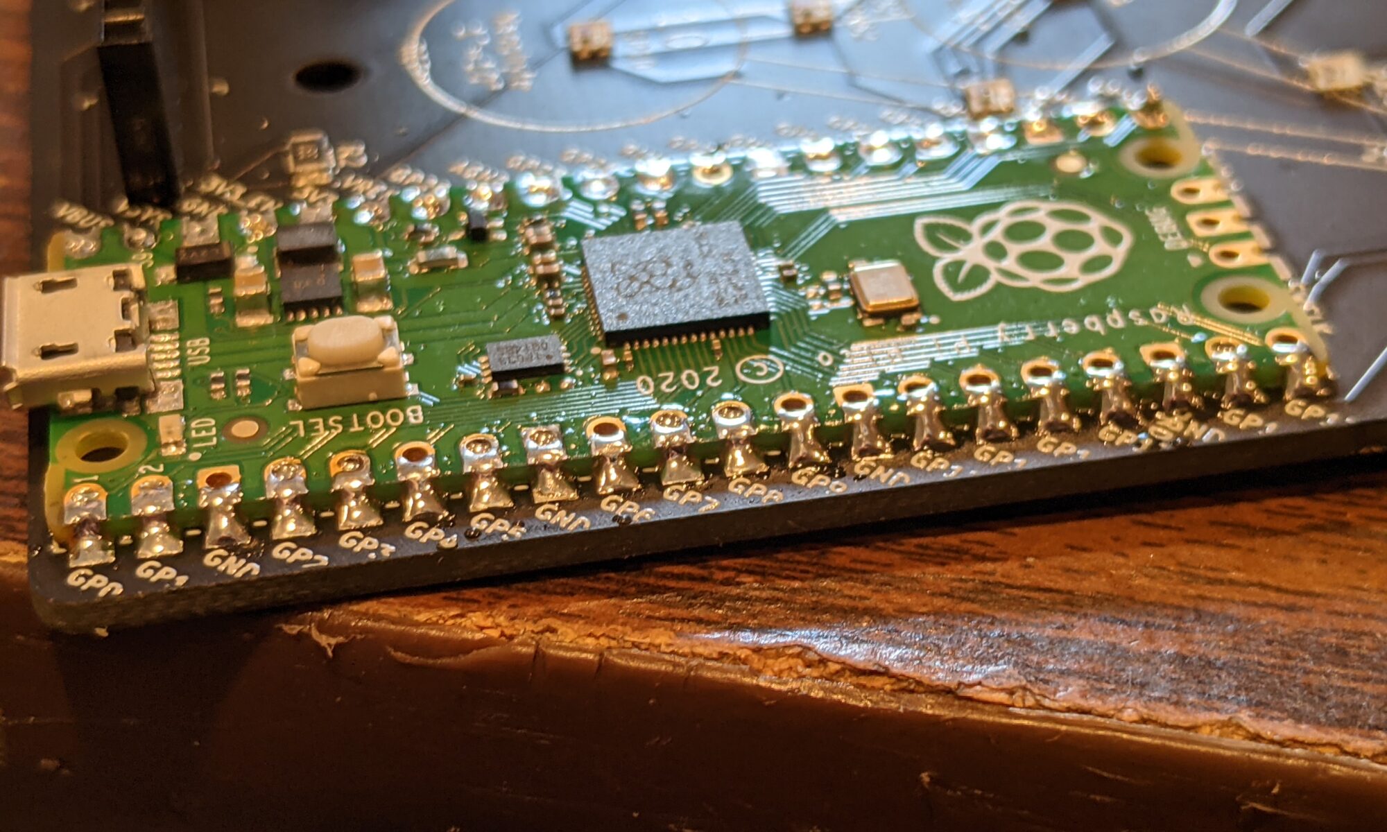
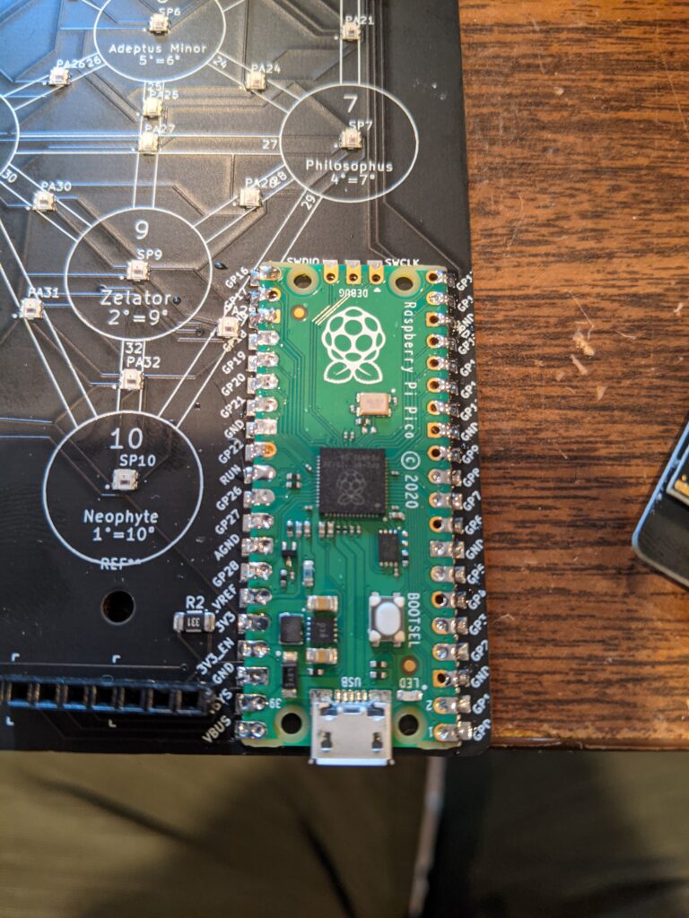
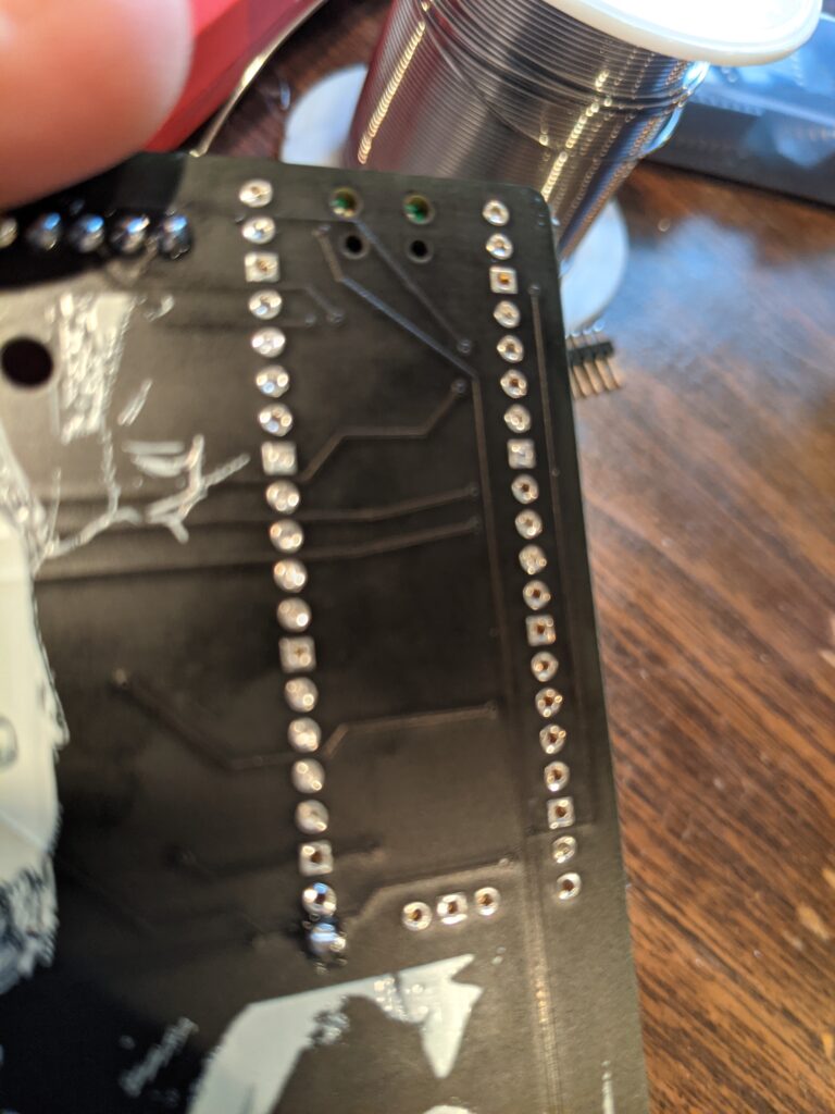
I was assembling the last of batch 1 earlier today, and decided on a whim to try headerless soldering directly to the pads with regular solder instead of paste. I used a 20-pin header temporarily on the left side to hold the pico in place on the board, soldered down the right side, then removed the header and soldered down the left. It worked great. It’s the best of both worlds. It saves wasted time with headers, cuts soldering in half, and keeps unsightly pins from poking out the bottom of the board. Just like regular thru-hole soldering, problems are visible. Bridging is not usually a problem, the solder tends to stick to the pads on the board as well as the generous copper pads on the Pico. All I need to do is make sure there’s a nice ramp from the upper pad, waterfalling over the castellated edges and onto the board pad.
If you ever have the urge to base a PCB around the Pico, consider this option.
Yes, we’re aware you can get the RP2040 chip on its own without the Pico, but one of our members bought a whole REEL of Picos, so it made sense for us to do this.
I gave a silly little “Intro to KiCad” presentation at our meetup last night, before the weather came and insisted we not congregate outdoors.
I shit you not, it happened almost too fast to document. “Oh look, the sky is threatening. Oh wow, the wind is picking up. Better get the electronics inside. Oh, there go the beer cans and a dessert plate. Holy shit.
Then everyone scattered home, and it really came down. We actually had hail. It was the first time hearing hail in our house. People were concerned. The cat was concerned.
Anyhow, I wanted to relay a problem/solution I ran across yesterday, because I hadn’t come across this particular solution to the problem in my Googling, and maybe this will help someone.
PROBLEM: When trying to do a 3D view, you get the dreaded “Cannot determine board outline” message and it will not properly render your board shape.
VARIANT 1: KiCad provides coordinates to look at. In most cases, this is because your board edges aren’t properly connected and locked together. Go around the perimeter, zoom in very close, and click both lines, observing where the square marking the end of the segment appears. If they are in the exact same point, they are locked together, move on to the next one. If you need to move one, move it until a circle with a square inside appears, that’s the locked/connected indicator while moving the line.
VARIANT 2: KiCad provides no further information, just the subject error message. This one took me a few minutes. I walked the perimeter and everything was fine/locked. I turned off all other layers’ visibility except for Edge Cuts and could see no stray segments. I was confused. So I went old school. Knowing that all of these files are just text files with information, I grepped the .kicad_pcb file for “Edge” and was treated with the following:
My first clue was that my board shape was a rectangle and there were five segments described. The second clue is that fifth segment was too short. Ridiculously short. Invisibly short. So I zoomed in at those coordinates, and sure enough, there was a stray dot of edge cut sitting there that couldn’t be seen without the zoom. I removed it, then everything was fine.
Documenting here in case it helps others. But if you don’t move your board outlines much, and don’t accidentally draw on the edge cut layer and forget it, this probably won’t happen to you.
It occurs to me that this happens frequently with other layers, I often end up with an extra dot of something that I discover later when zoomed in. It might be useful to have a routine or view that just highlights every sub-millimeter unnecessary portion of wire, mask, edge or silkscreen that was probably left there by accident. 🙂
So this thing we’re working on, you know. This is the second or third iteration of an idea, and it finally got enough momentum to, you know, be something. Or become something.
Originally, we were going to do it on maybe an ESP8266. Then maybe an ESP32. Then the Pico came out, and we’re like, fuck it, let’s ride the wave of momentum of this new awesome microcontroller and see what we can do with it.
Well, it’s amazing, and awesome, and wonderful, BUT it lacks wireless communication.
And we started looking into what it would take.
And found a couple of articles that piggyback an ESP32 to handle the comms.
Meh. Nah. Number 1, if we wanted an ESP32, we’d just use an ESP32. Number 2, we don’t need, or even want, full wifi. We just want communication between units. For this thing of ours.
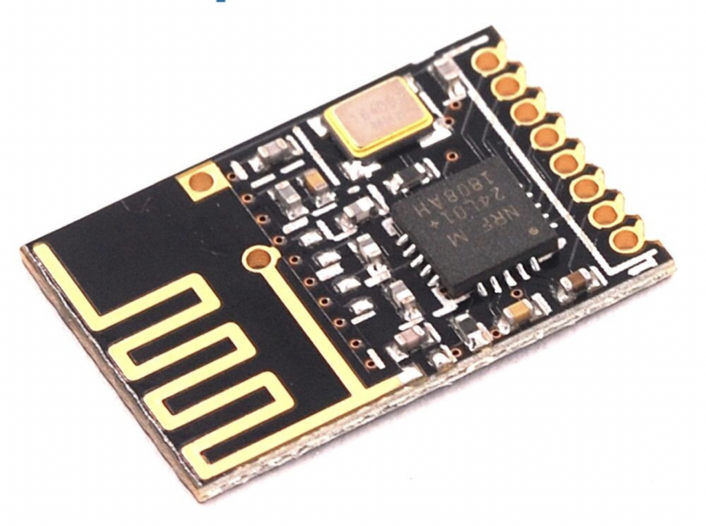
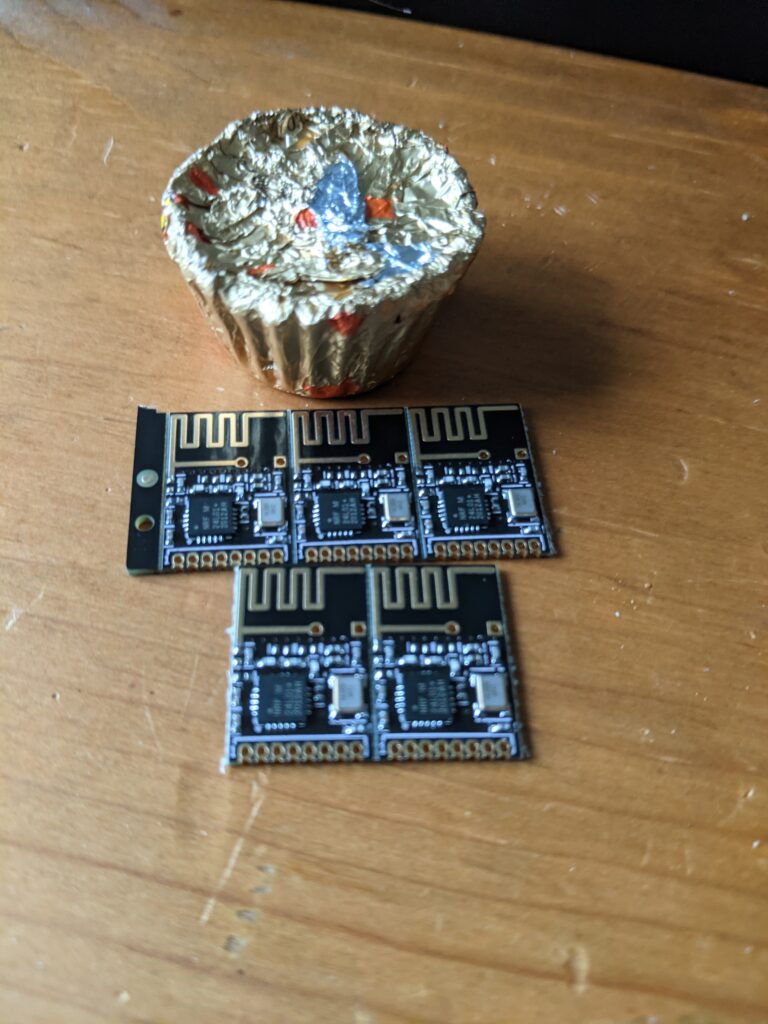
Then I saw that I can get this model of the NRF24L01+ for just a buck a piece.
Like the Pico, it has those glorious edges that can either be thru-hole (albeit half pitch) or surface-mount. I love that, you all know I love that. I love that you can mount it on a board and the other side of the board can be virtually unmolested.
So I picked up a few for testing.
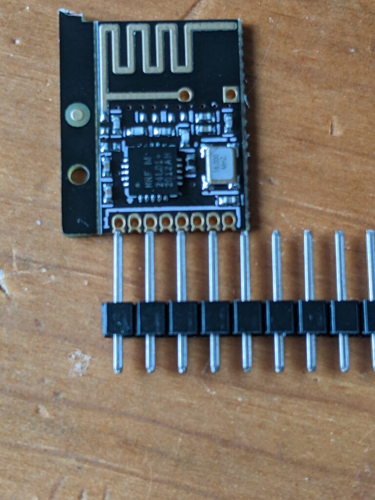
And dang, they’re small.
And this half-pitch bullshit presents a problem for traditional breadboarding.
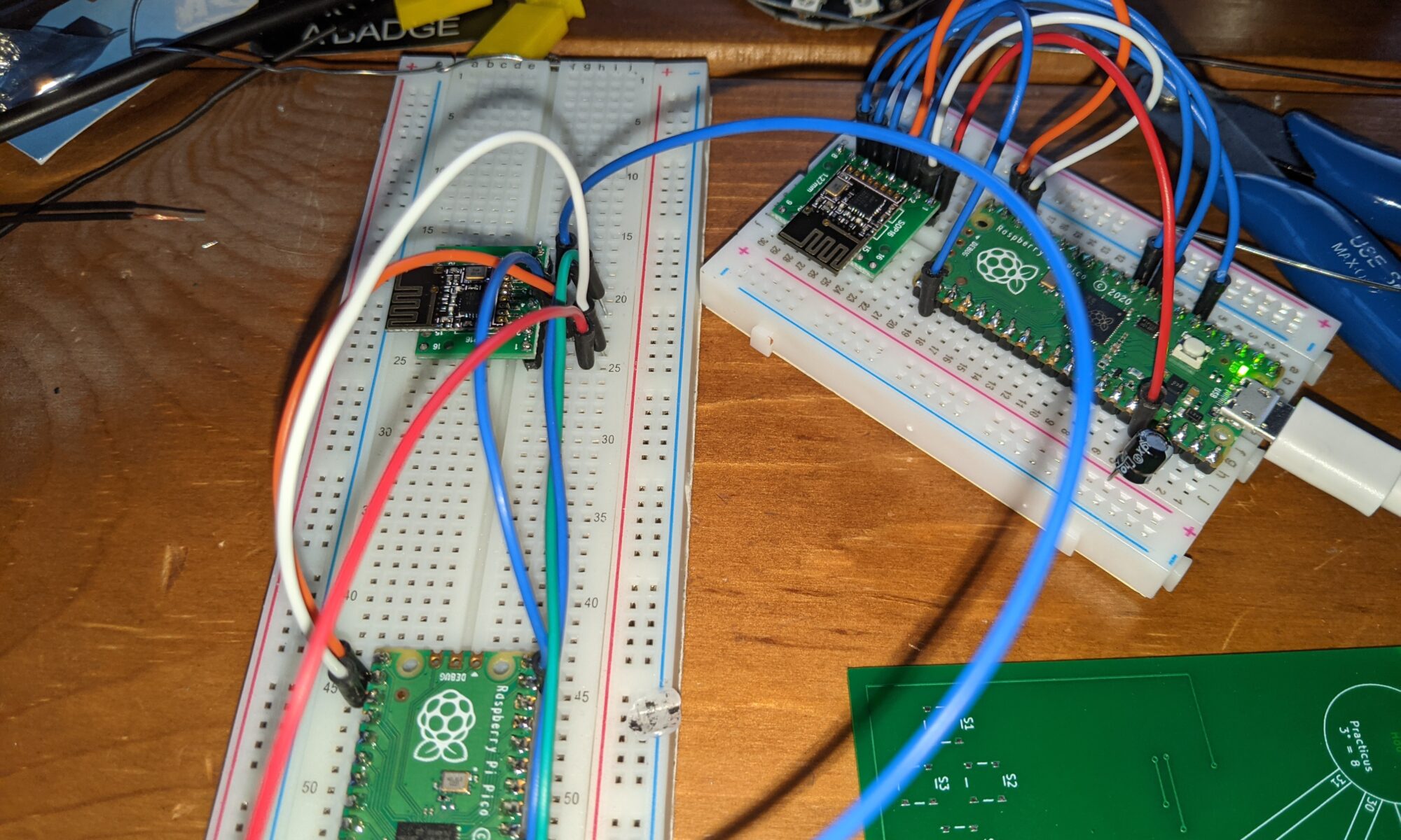
Fortunately, I have some SMD breakout boards that fit this perfectly. Let’s put a couple together for testing.
OK, now that I can breadboard this, let’s find some software for it.
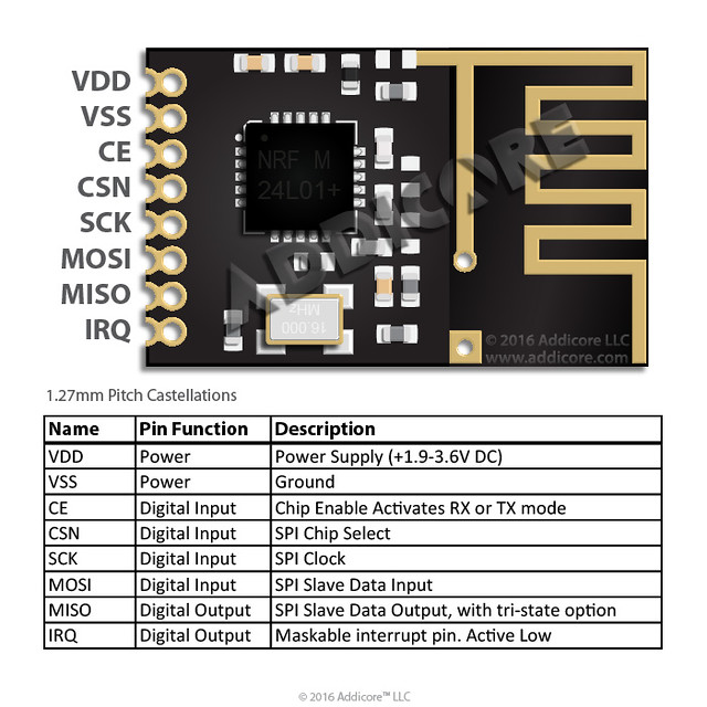
and connect the appropriate pins on your Pico to the correct pins on the NRF24L01+:
So I did all this, and fixed the connections so that I wasn’t getting hardware failures. I did it twice, because the example code has a master function and a slave function. Yes, I know, these are now outdated terms. Maybe someone should tell them to update it.
Anyhow, nrf24l01test.master() broadcasts a packet with the milliseconds, and wait 250ms for a response. nrf24l01test.slave() will listen for those packets, and if one is received, send a response. I ran it, excitedly — one pico/nrf24l01 assembly running nrf24l01test.slave() and another running nrf24l01test.master()… and…
Nothing. Response timeout. Consistently. So I googled a bit, and found that with some devices, a capacitor is needed “to smooth the current.” Some docs say 10uf, others say 100uf. I found that 10uf cut the failures to about half, and 100uf eliminated the failures. With a 100uf capacitor between VDD and GND on the transceiver, responses come back steadily, even if I take the sender into another room, 30 feet away, even to a different floor of the house, with walls in between. I’m impressed.
Interesting info: I had so much trouble finding a KiCad symbol and footprint for this device that I started to build my own. But then I found one by accident in the mysensors repo. Important note: Pay attention to the symbol on this one. The symbol as provided in mysensors has VCC on pin 2 and GND on pin 1, but the units I received have VCC on pin 1 and GND on pin 2. I suspect that’s the reason for one review of the unit I ordered stating that the pinout was nonstandard. I don’t know what’s official and standard, but the pinout on the units I received match the photo above, so maybe mysensors is wrong, or maybe there is no standard. Just be aware so that you don’t smoke your transceivers.
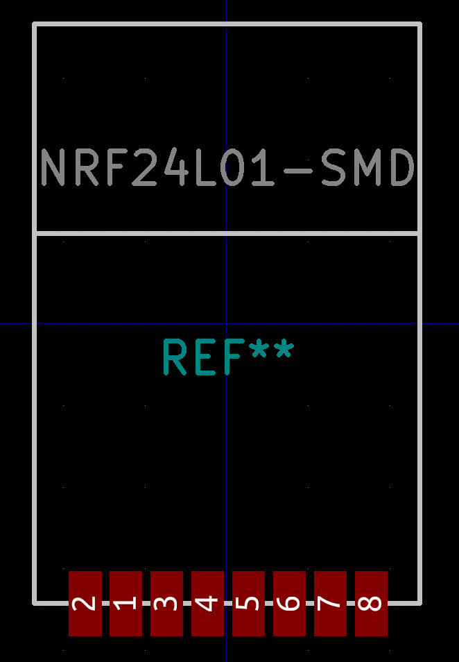
Update: LOL. I take it back about the pin 1 vs 2 confusion. Look what they did in the footprint!
When I finally got my hands on some Pico microcontrollers, I was excited to see what they could do. But I was used to the Arduino infrastructure and wanted to explore the Pico on its own terms.
Obviously MicroPython is the easy choice. Once the Pico is flashed with MicroPython firmware, you can write your code in Thonny and just save it straight to the Pico from within Thonny. Easy peazy.
Coding in C requires a bit more effort, especially at the start. You need to get the compiler installed, which varies by OS, and since I develop on a Mac with the M1 Silicon chip, it’s even more obscure for me. Fortunately, it’s all right there in the docs. Specifically, the “Getting Started” document, chapter 9, page 37. An architecture flag allowed the brew command to work, and I was off to the races.
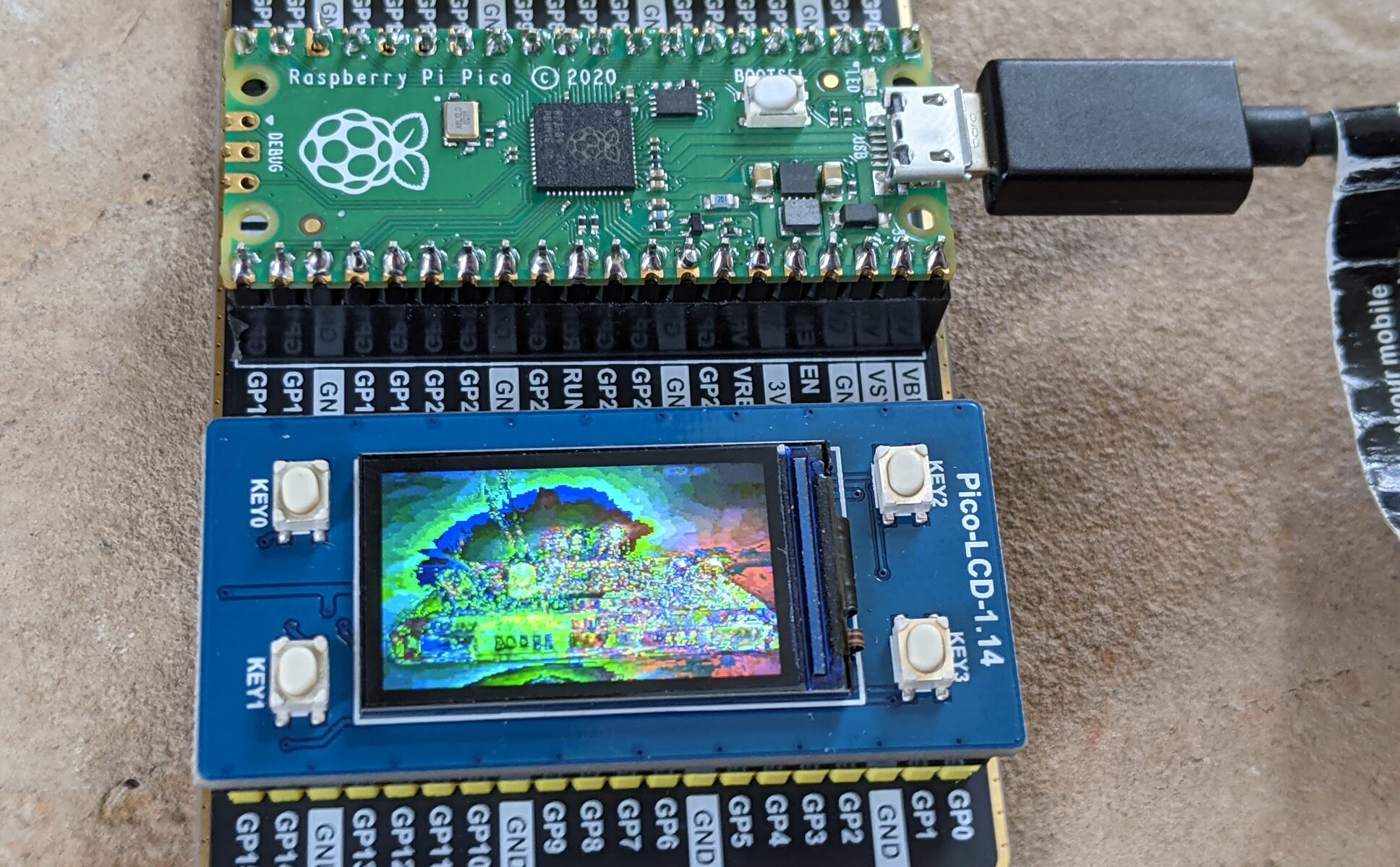
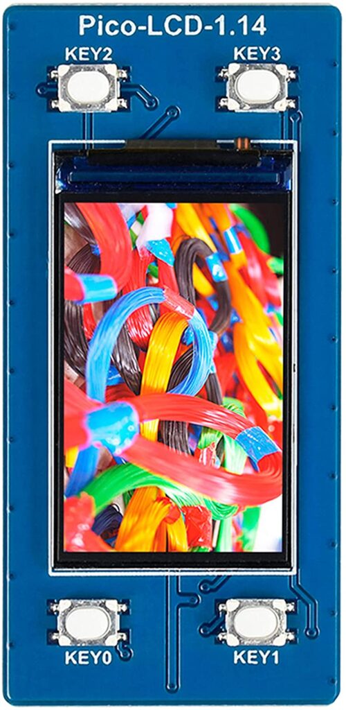
Pin stuff is easy. I know I can do that. I wanted to skip to some wacky complicated stuff. So I started with the Waveshare demo for the Waveshare Pico-LCD-1.14 display hat with buttons. I decided i wanted to modify that demo to display my own image instead of the stock image. After some trial and error, I was sort of able to do so.
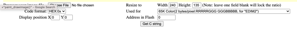
The image is stored as a c hex array. Getting that file exactly right was time-consuming. I didn’t see an image converter in their examples arsenal, so I found this one online. By tweaking the settings a bit I was able to get an image to display .. sort of. The color mappings are different somehow. Maybe 65K colors isn’t that many after all. I’ll have to mess with it with a more legible photo.
Original photo for reference:
The display is 240×135 and 65K colors. I’ll update this post when I figure out more. This is just to make it a little bit easier for those who want to get into C programming on the Pico but don’t know where to start.
Also, these kids will show you the general build environment / compile process completely if you live in Ubuntu-land. Amazing.
Our next meeting will again focus on the Raspberry Pi Pico. We are looking at, weather permitting, an outdoor in-person meeting next Monday. Stay tuned in the Discord to see if it’s happening.
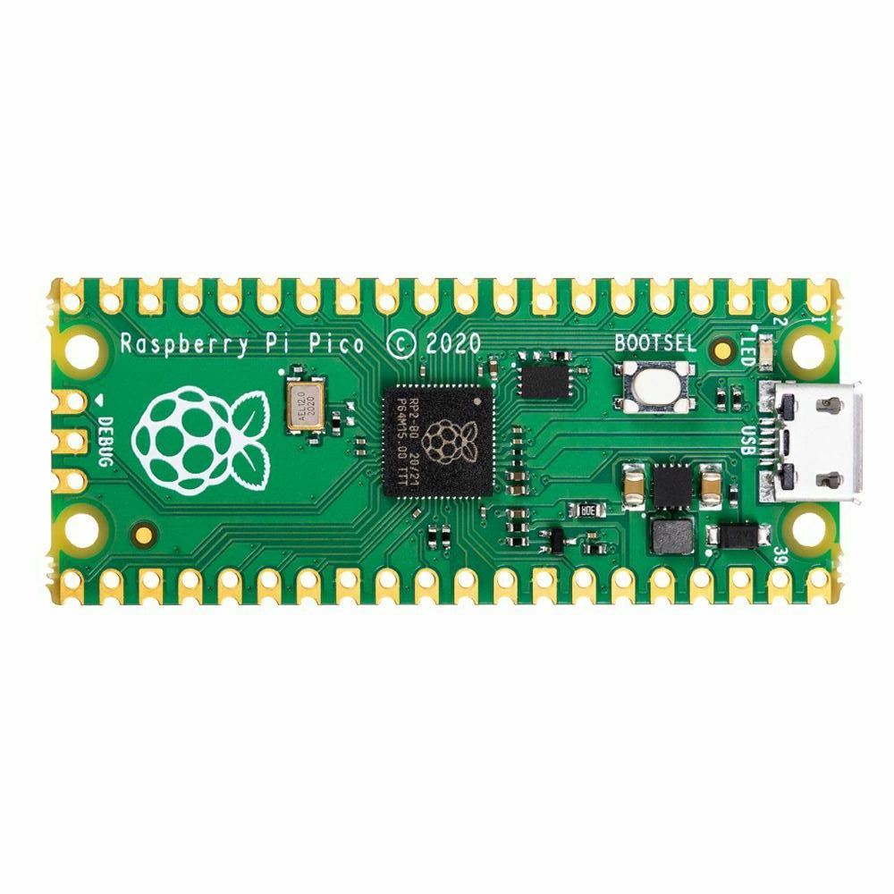
So, our regulars will know that one of our founding members, in a moment of extremely questionable judgment, purchased an entire REEL of Raspberry Pi Pico microcontrollers. If you’re out of the loop on this device, it’s closer to an Arduino than the previous iterations of the Raspberry Pi. While the Raspberry Pi 2, 3, 4 and Zero are all tiny computers onto which you install an operating system, the Raspberry Pi Pico is a microcontroller, onto which you flash firmware and code.
The Pico, as a microcontroller, has a lot of things going for it. It’s very small, it’s light weight, and the castellated edges provide a lot in terms of mounting flexibility. You can either mount it thru-hole or surface-mount it on pads!
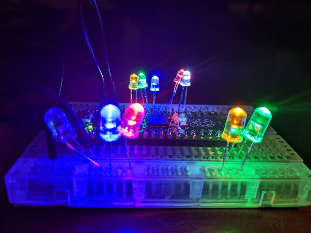
The easiest way to use it is with MicroPython. By flashing the Pico with MicroPython firmware, it provides and environment that allows you to very easily drop new MicroPython programs onto the Pico just by pressing the boot button and having it mount to your computer as a storage device — programs that can easily interact with LEDs, sensors, servos, etc… basically anything that a microcontroller can do by sending and receiving data on its I/O pins, this little baby can do. See the recent post on the vintage powered breadboard for an example of the Pico in action.
This also includes using tiny OLED displays. For example, the Waveshare 1.14″ display for Pico — this is available in a “hat” format, meaning it sits right on top of the Pico once the headers are installed in the correct direction. At that point you can easily build a 3d-printed housing for it or include it in a larger project’s design. It conveniently includes four buttons to drive any menus you come up with or provide some other sort of input.
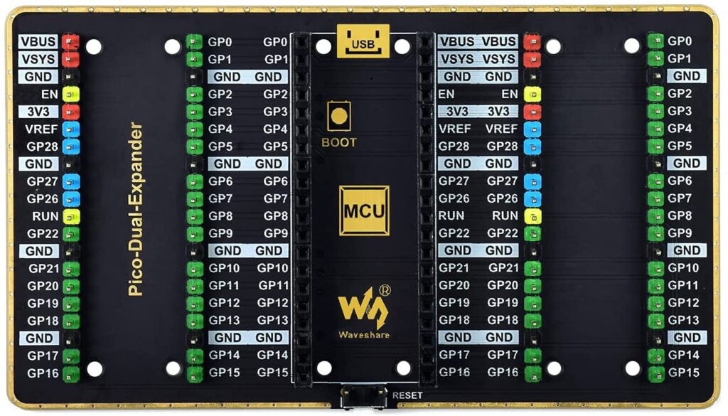
Then there’s the GPIO expander, also by Waveshare. It’s a single board, on which you mount the Pico, and it splits all of your GPIO pins into left and right versions. So if you have two different devices you want to connect (and there are no conflicting pins), it’s pretty easy to do that.
If you were around a few weeks ago, our man Kevin provided a really cool demo of reverse engineering using the Pico.
If the weather holds out, our next meeting maybe in person, outdoors, and we’ll have some cool Pico stuff to demo, build, and play with.
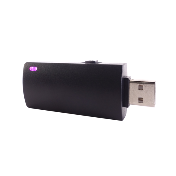
I decided to dust off my Hak5 field kit and refamiliarize myself with all the tools. I have the bashbunny, the LAN turtle, the rubber ducky, and a bunch of utility adapters. I also have a wifi cactus in there, but I’m pretty sure I picked that up separately.
I started with the Bashbunny, since it’s so versatile. I won’t address advanced topics like locked PCs in this post, this is very basic bashbunny talk. So the scope here is “some dumbass left me unmonitored access to a PC.” Either unattended, or “here, you drive while I go get a drink.” Yeah, don’t do that with someone who might have these tools and tendencies.
So the first thing I noticed was that it was out of date. Fortunately, Hak5 has very usable instructions and tools for making it current.
So I went through all that process, bringing my payloads and firmware up to current levels. It was a fun exercise.
The first script I ran was recon/MacProfiler. I set the Bashbunny to Arm, copied the payload.txt into switch1/, ejected it, switched the Bashbunny to position 1, and reinserted it.
Ran once, and it left the bashbunny mounted. The second time I ran it, it successfully ejected itself, which is important if you’re trying to be a bit stealthy. At some point I’ll investigate that further.
It worked well. It gathered a list of all of the /Applications on my MacBook Air, a list of all users, and all the networking information I might need. Oh, and a list of things that startup automatically. All of this is tremendously useful for recon, so that you can craft a later attack for next time you have access to the same PC.
Next, I tried macinfograbber. Similar concept, but it’s specifically crafted to grab a copy of any spreadsheets (xls/xlsx) in the user’s Documents directory. By extension, of course, this could mean whatever type of files you’re specifically aiming for.
(arm) (eject) (switch) (reinsert)
OK, this did some stuff, then ended with a red LED indicator on the bashbunny. This translates to “no files found” according to the script. Kind of surprising. Do I really have no xls/xlsx files in my Documents directory? Let’s see… Hmmm, yep. I do. Why did it fail? At first I thought maybe it was spaces in the filename and a poorly-written script, but I renamed it to a single word and tried again and it continued to fail.
So I dug deeper. Here’s the command that macinfograbber uses to grab those files:
And here’s the problem. I’m assuming these scripts were written back in 2017 when the Bashbunny was fresh. In 2019, Apple switched from bash to zsh on the Macs. And apparently, zsh fails this command if any glob fails for safety reasons. So that line will need to be rewritten, or just broken out into individual commands.
More on the Bashbunny later. I plan to dig deep through the whole payload library for a 2021 refresh, because it’s still useful. Although you might want to remember to take your USB-C adapter with you for modern MacBooks. 🙂
When I first saw this DIY Raspberry Pi Cyberdeck, I knew I wanted to build it. I love the aesthetic, and I already have most of the parts. Element14 was kind enough to present most of what I need via direct links.
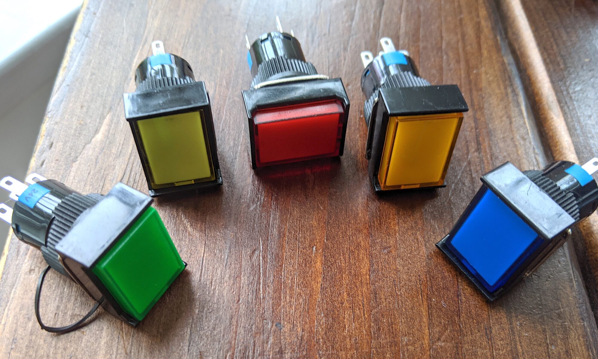
And then I saw the price. Those beautiful rectangular switches to the right of the screen? Illuminated latching switches, $20 each! I just can’t stomach blowing $100 on switches for a DIY case.
So I started shopping. And damned if I didn’t find them ALL quite pricy. I must have shopped for over a week in my spare time, and really couldn’t catch a break.
Until I found these:
Amazon. $10.89 for five, around half the cost of ONE everywhere else. Ordered March 25, shipped from China, arrived today. Not bad for China.
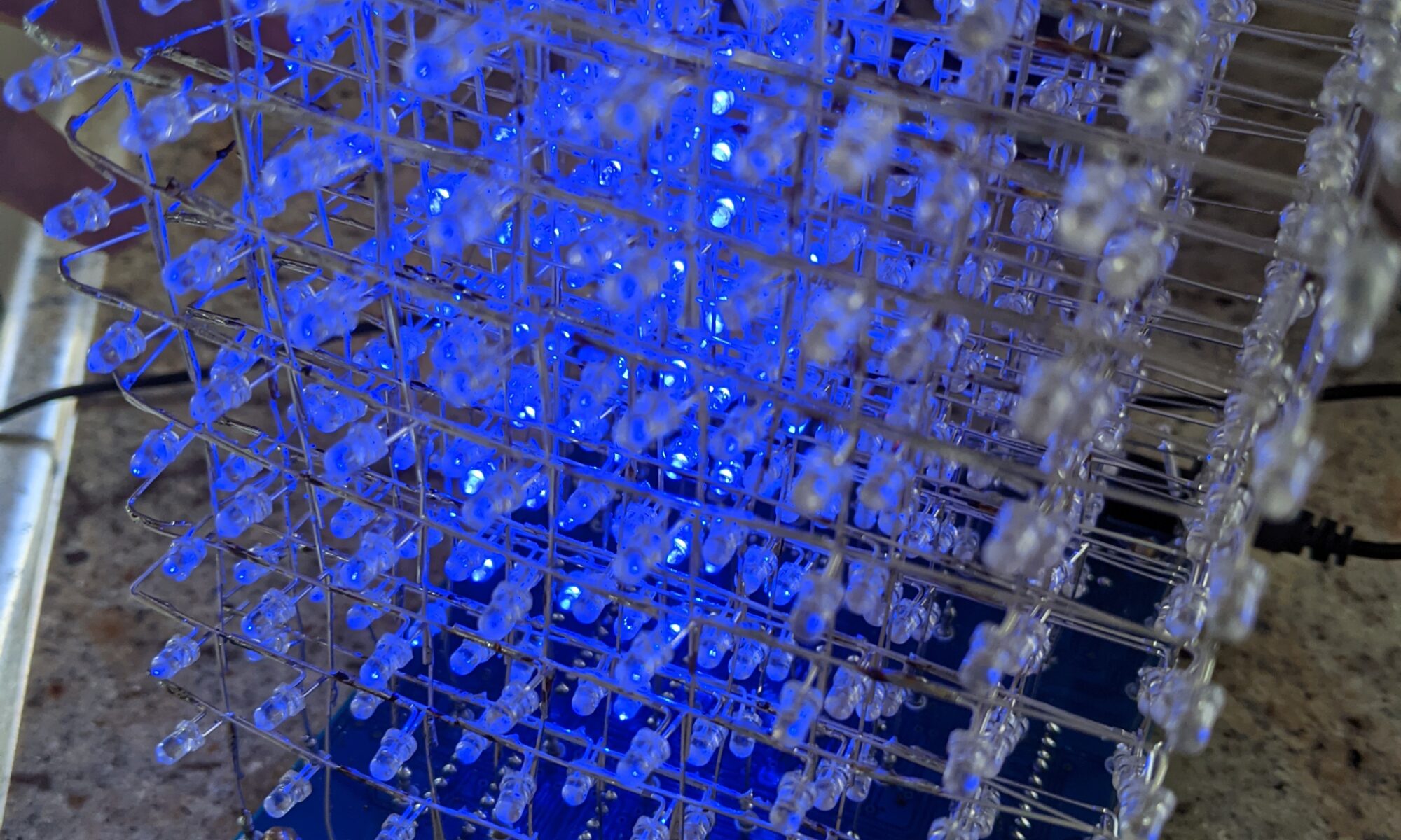
I finally picked up one of those 8x8x8 LED cube matrix kits. I’m a sucker for blinkyshit, all the DC540 regulars know that. I’m doing the rare thing here in documenting before the resolution of all of the issues, just because the processes deserve documentation, I think.
I am by no means a hardware expert. I stand on the shoulders of the entire internet when it comes to mucking about with programming microcontrollers. I’ve gotten better, but it’s still not innate to me the way other aspects of technology are. There are just too many microcontrollers, and too many ways of poking at them. I2C, SPI, JTAG, sometimes it seems almost overwhelming.
But here we are, with this STC12CA60S2 microcontroller, already installed on the PCB. I went through all the steps over the weekend of soldering all 512 LEDs and the other chips and small parts. I don’t know about you, but when I get close to the end of a project like this, the anticipation starts to really kick in. If I’m not careful, it’s easy to get sloppy and make a stupid mistake. But I didn’t, this time. I did find myself short on LEDs. The kit came with extras of most of the small parts, but inexplicably, only the exact number of LEDs, and two of them were DOA. So I had to order replacements from another supplier, and I didn’t think to order long-leg LEDs for the replacements, so I really had to work a bit to fit them in.
So here we are, it’s all assembled, looks great from a distance, but up close you can see my sloppy skills. This is how the Captcha protections should work, they should evaluate us on our assembly skills. Clearly I am not a robot.
From the instructions I found, the STC12 is supposed to be pre-programmed, and I should just be able to apply power and see the animations. No such luck. It illuminates a block of LEDs, but no animation. To be thorough, I double-checked all the chip orientations, and double-checked all LED paths by using my bench power supply and applying 3V to each power vertical and grounding each ground horizontal to confirm that every LED is “addressable.” I suspect from Internet research that they lapsed and sent me an un-programmed STC12, because it’s documented that this happens. Not a problem, I’m up for the challenge, I’ll figure this out.
Let’s see. It wants a UART USB TTL serial device. Four-pin header. VCC, GND, P30 (RX) and P31 (TX). Well, I don’t have the Adafruit programmer they recommend, but I do have a FTDI FT232R. Let’s give that a shot… Nope, it doesn’t seem to recognize the power cycle, it stays on “Waiting for MCU…” even though I cycled power. NOTE: during this process, the devices is powered, 5V, by the USB programmer. Interestingly, and the Internet backs me up on this, the power light remains dimly lit even with the power button off. Several sources report that parasitic power leaking from the TX line can interfere with the power cycle reset process, preventing this from working. It’s possible this is only an issue on these FTDI programmers, and maybe the problem will go away when I use the recommended Adafruit programmer, which arrives today.
But I’m impatient, I WANT IT NOW! So I started scouring the lab to see if I have any other options available to me. Hmm, I have a Bus Pirate, the Swiss army knife of microcontroller programmers. I spent about an hour last night learning it and futzing with it. The Bus Pirate is interesting but cumbersome. You plug it in, then you serial directly to it (I use screen on the Macbook) and configure it for the purpose intended using a manu system. Then I exit screen and do what I would normally do with a dedicated programmer.
The Bus Pirate doesn’t seem to handle the power situation correctly either, but in a different way. It doesn’t seem to know how to power cycle correctly in UART mode. Even if I set power on before running the stcgal command, it shuts power off when I initiate the sequence and never turns it back on again. What if I disconnect power and ground from the programmer to the board and use the cube’s external power supply? I’ll try that after this post, but I don’t have a lot of hope. I tried this tactic with the FTDI and didn’t see any difference. I wonder if part of the process is the programmer detecting voltage via the same pins it provides voltage on. UPDATE: Tried that on the Bus Pirate, no luck. Also tried another suggestion, putting a 10K resistor inline with TX to keep that parasitic power at bay. No luck. Hopefully the Arduino programmer will work.
Another option is that I have one of those ZIF-socket chip programmers. That’ll be a last resort. I prefer not to pull chips off the board, even though they’re socketed, because of the potential for excessive bending and possible breakage of the pins.
Oh well, one way or another I’ll update this already-too-long shitpost later today. I’ve got at least two paths left to explore today.