

A few weeks ago, I came across this vintage powered protoboard system on FB Marketplace. It seemed to be priced reasonably for its functionality, and the owner stated that it was working. So I snagged it. I admit I was tired of working with individual breadboard strips and cheap chinese power supplies, and wanted something larger and more stable. The fact that this provides 12V and 5V and a number of lamps, switches and buttons made it much more attractive.
I started looking online for a manual for it. It’s not a complicated unit, but I wanted to know what the manufacture intended for use case and workflow. So far I have been unable to find much on it other than a brochure on archive.org and a YouTube video from “IMSAI Guy” who picked one up for free at a junk drop-off location in Santa Clara. IMSAI Guy’s video was extremely helpful, as it gave me some clues about usage and expectations. Much of the board is unlabeled, but fairly intuitive. +12V and -12V terminals on the lower right, and two bare GND terminals near the bottom of the unit, are the only terminals that are labeled.
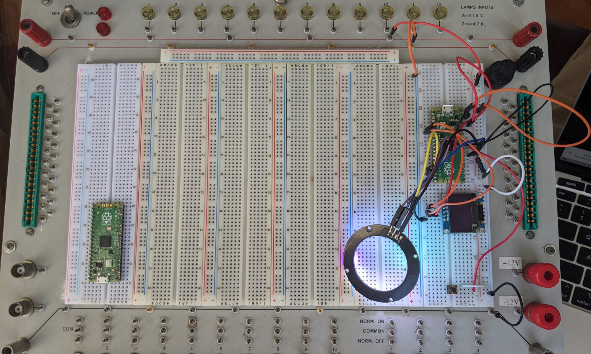
On the video, IMSAI guy shows two pairs of red terminals near the top, one on the left side and one on the right, and it sounded like he was saying that they are 5V terminals tied together. Here’s where mine starts to differ. Rather than two pairs of red, I have two red/black pairs. I powered it up and grabbed the multimeter. Measuring from red to ground gives the expected 5V. Black to ground gives zero. Is this another ground? Hmmm not quite. Red to black gives 4.7V. At this point I’m a bit confused. It’s definitely the same model as in the video, but it’s different.
So I went through and tested the other features. All twelve of the lamps are functional and pre-grounded with a 4.7K resistor inline, all you need to do is tie them to power >1.5V and they light up. The ten switches are nicely configured, they provide patch points for normal on and normal off. Same with the four momentary button switches.
There are edge PCB connectors on each side which I can’t imagine using at this point in time, and a pair of BNC jacks on the left side. Those could be interesting.
So I built a couple of Raspberry Pi Pico example circuits and powered them up, just for the photo op, and to put the thing through its paces.
But I was still perplexed about the black terminals. Why does mine have different terminals than IMSAI Guy’s? I made a mental note to open it up later and figure this out.
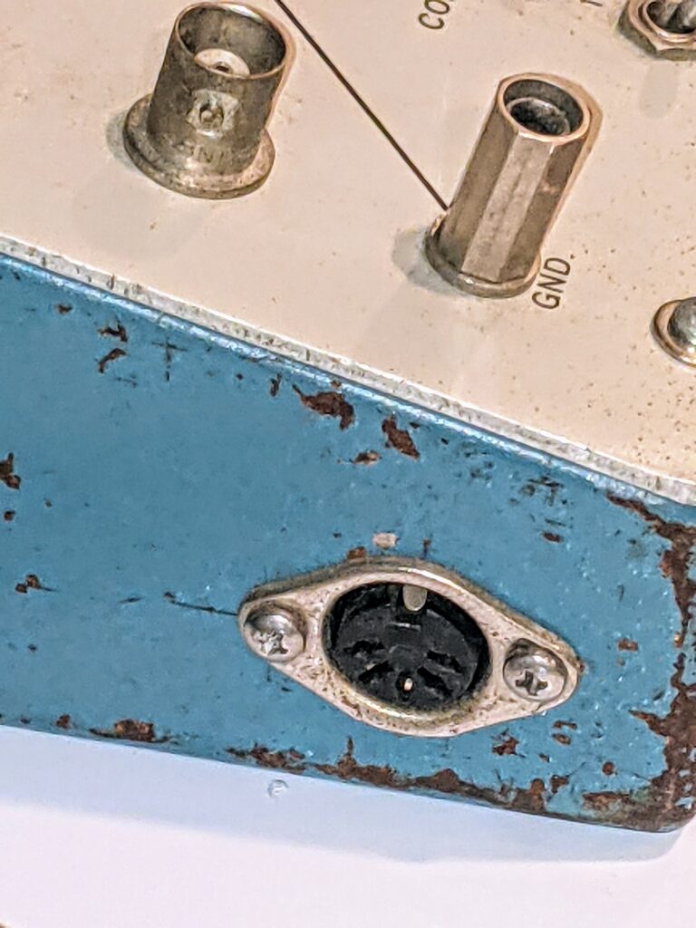
Then last night I looked at it from a different angle and noticed something I hadn’t seen before. There’s a DIN-5 connector on the left face of the unit that I hadn’t noticed before. What possible use for a DIN-5 connector would this thing have? I opened up IMSAI guy’s video again, and watched as he spun the unit. Nope, I don’t think his has this. Now I HAVE to open it up.
WOW. So mine is a modified unit. Getting the docs probably wouldn’t help at this point, unless this is a later model and how it was released by the manufacturer. (shrug).
I found another expired auction listing for one of these, and it did NOT have the DIN-5. So either it’s not stock or it’s a later model.
Opening up the unit, I find another board that’s not on the other two examples I’ve found. Over to the right is a more modern power supply than the brick transformer it came with. An E59712 board. And now the light bulb in my head goes on. Maybe, since this board seems to have adjustable voltage at R21, maybe it’s feeding the black terminals somehow, providing an alternative to just +/-12V or +5V. Further research required.
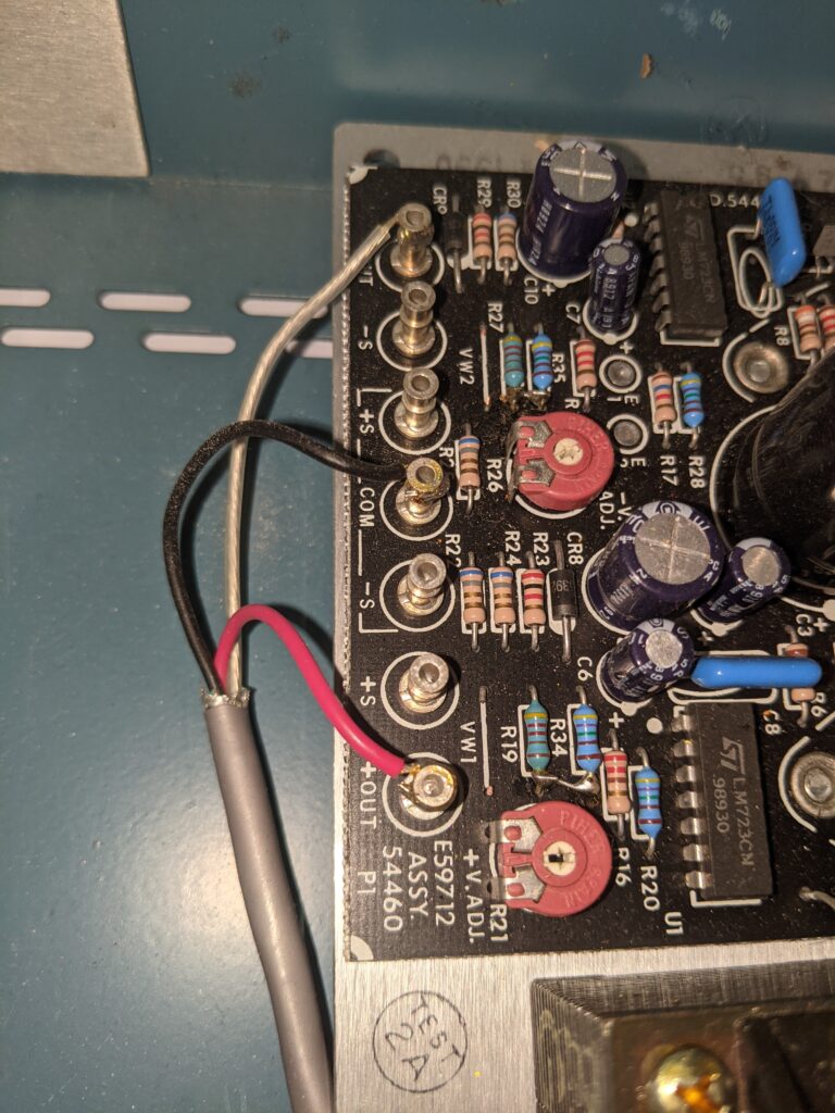
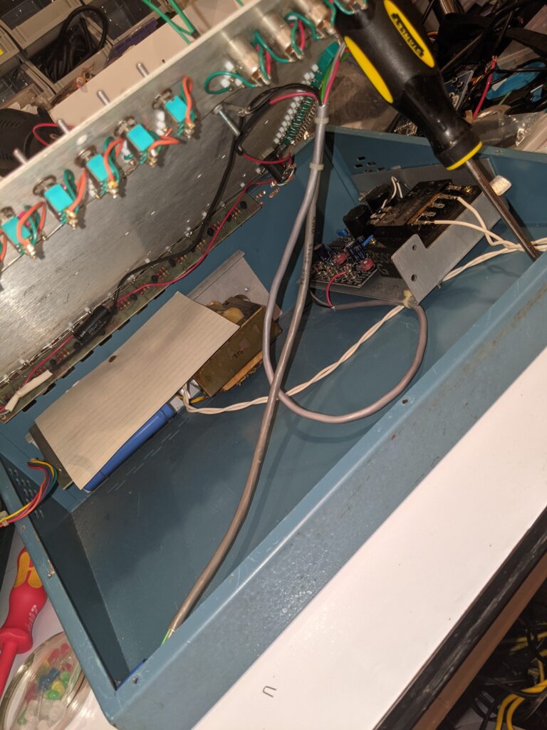
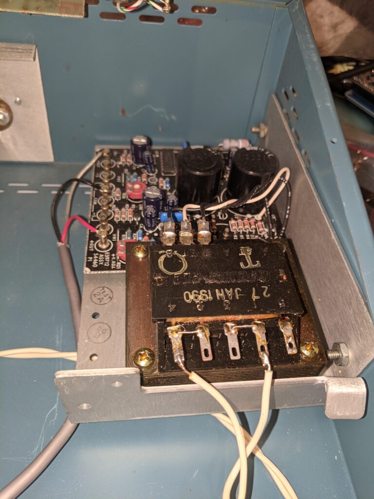
Add to that the fact that this subassembly is tied to the main power supply, the DIN-5 connector AND the surface board, and I’m starting to get a picture of things. I’m going to have to test more, but I feel like either this is a supplemental board designed to give more flexibility to the unit, or the main power supply died and this is a more modern replacement that was shoved in. I really am curious about the DIN-5 use case, though.
Mine had a SUNY asset tag on it, in case you’re curious. Anyhow, more digging later.
Update: Here’s a PDF of the original brochure. Not as good as a manual, but useful just the same.