
So this thing we’re working on, you know. This is the second or third iteration of an idea, and it finally got enough momentum to, you know, be something. Or become something.
Originally, we were going to do it on maybe an ESP8266. Then maybe an ESP32. Then the Pico came out, and we’re like, fuck it, let’s ride the wave of momentum of this new awesome microcontroller and see what we can do with it.
Well, it’s amazing, and awesome, and wonderful, BUT it lacks wireless communication.
And we started looking into what it would take.
And found a couple of articles that piggyback an ESP32 to handle the comms.
Meh. Nah. Number 1, if we wanted an ESP32, we’d just use an ESP32. Number 2, we don’t need, or even want, full wifi. We just want communication between units. For this thing of ours.
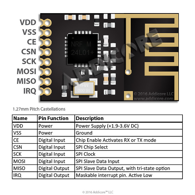
Then I saw that I can get this model of the NRF24L01+ for just a buck a piece.
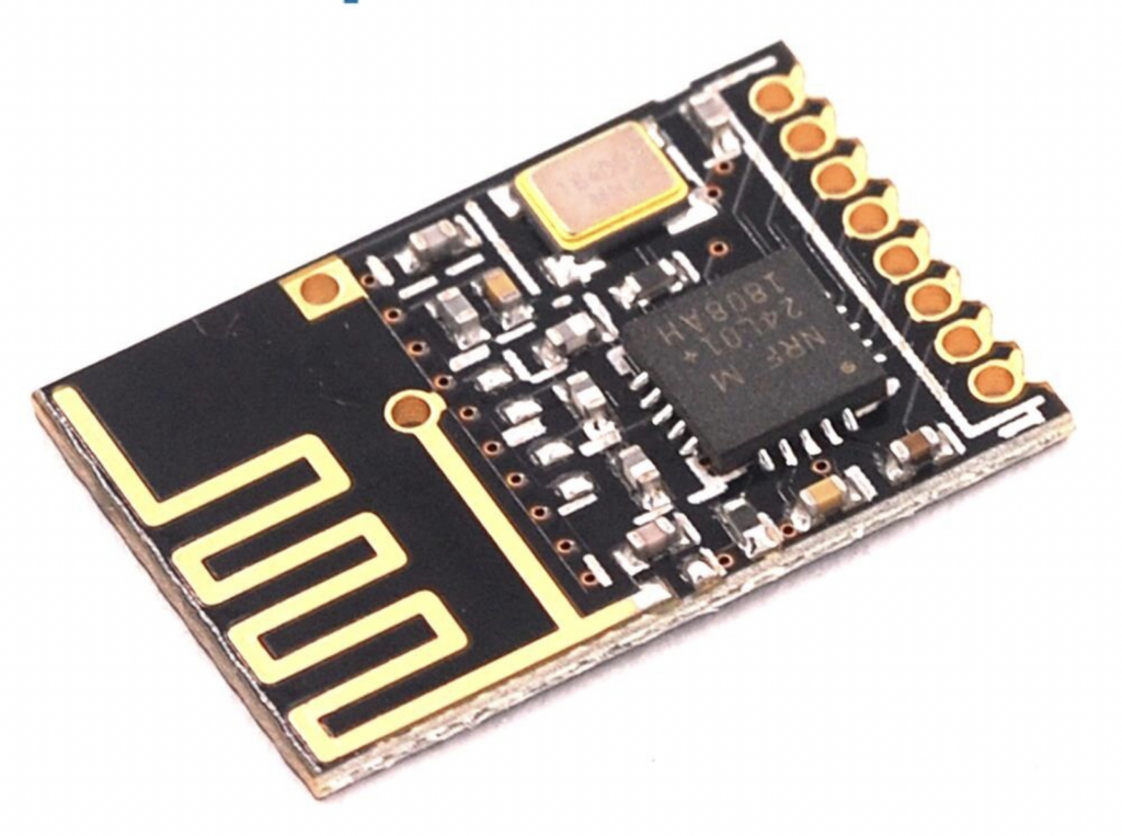
Like the Pico, it has those glorious edges that can either be thru-hole (albeit half pitch) or surface-mount. I love that, you all know I love that. I love that you can mount it on a board and the other side of the board can be virtually unmolested.
So I picked up a few for testing.
And dang, they’re small.
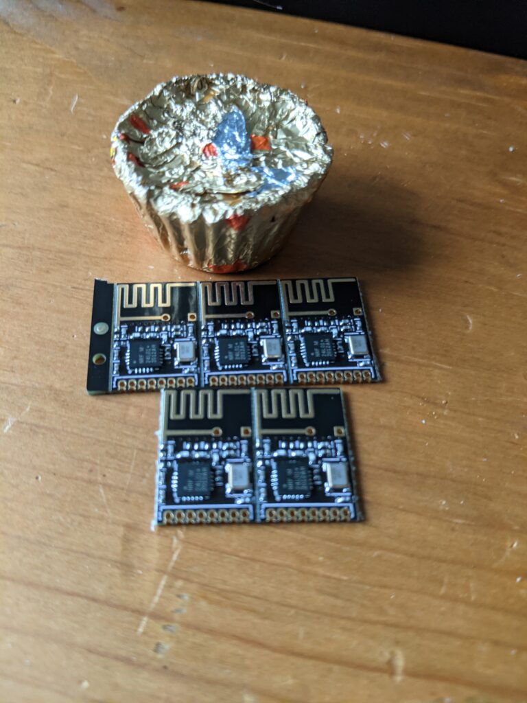
And this half-pitch bullshit presents a problem for traditional breadboarding.
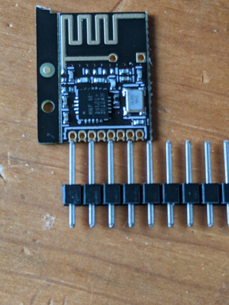
Fortunately, I have some SMD breakout boards that fit this perfectly. Let’s put a couple together for testing.


OK, now that I can breadboard this, let’s find some software for it.
NRF24L01 drivers for Micropython
These drivers won’t recognize the Raspberry Pi Pico without modification. You need to add a configuration line in nrf24l01test.py:
if usys.platform == "pyboard":
    cfg = {"spi": 2, "miso": "Y7", "mosi": "Y8", "sck": "Y6", "csn": "Y5", "ce": "Y4"}
elif usys.platform == "esp8266":  # Hardware SPI
    cfg = {"spi": 1, "miso": 12, "mosi": 13, "sck": 14, "csn": 4, "ce": 5}
elif usys.platform == "esp32":  # Software SPI
    cfg = {"spi": -1, "miso": 32, "mosi": 33, "sck": 25, "csn": 26, "ce": 27}
else:
    raise ValueError("Unsupported platform {}".format(usys.platform))
Just add another elif stanza:
elif usys.platform == "rp2": #Pico
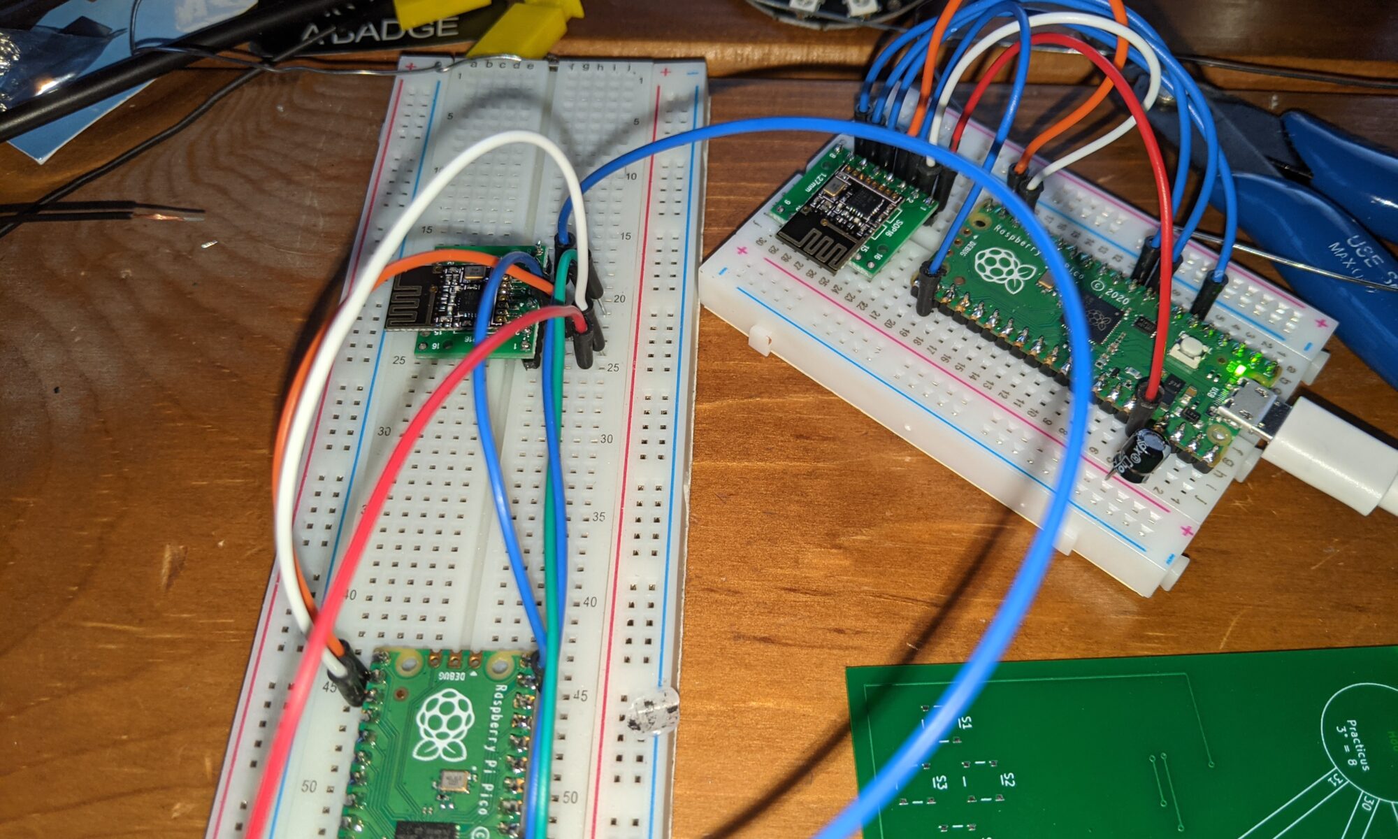
cfg = {"spi": 0, "miso": 4, "mosi": 7, "sck": 6, "csn": 14, "ce": 17} and connect the appropriate pins on your Pico to the correct pins on the NRF24L01+:
So I did all this, and fixed the connections so that I wasn’t getting hardware failures. I did it twice, because the example code has a master function and a slave function. Yes, I know, these are now outdated terms. Maybe someone should tell them to update it.
Anyhow, nrf24l01test.master() broadcasts a packet with the milliseconds, and wait 250ms for a response. nrf24l01test.slave() will listen for those packets, and if one is received, send a response. I ran it, excitedly — one pico/nrf24l01 assembly running nrf24l01test.slave() and another running nrf24l01test.master()… and…
Nothing. Response timeout. Consistently. So I googled a bit, and found that with some devices, a capacitor is needed “to smooth the current.” Some docs say 10uf, others say 100uf. I found that 10uf cut the failures to about half, and 100uf eliminated the failures. With a 100uf capacitor between VDD and GND on the transceiver, responses come back steadily, even if I take the sender into another room, 30 feet away, even to a different floor of the house, with walls in between. I’m impressed.
sending: 2802292 2
got response: 2802292 (delay 40 ms)
sending: 2802591 4
got response: 2802591 (delay 34 ms)
sending: 2802886 8
got response: 2802886 (delay 35 ms)
sending: 2803177 1
got response: 2803177 (delay 39 ms)
sending: 2803475 2
got response: 2803475 (delay 35 ms)
sending: 2803770 4
got response: 2803770 (delay 35 ms)
sending: 2804065 8
got response: 2804065 (delay 35 ms)
sending: 2804360 1
got response: 2804360 (delay 35 ms)
sending: 2804656 2
got response: 2804656 (delay 40 ms)
sending: 2804957 4
got response: 2804957 (delay 45 ms)
sending: 2805260 8
got response: 2805260 (delay 37 ms)
sending: 2805558 1
got response: 2805558 (delay 38 ms)
sending: 2805853 2
got response: 2805853 (delay 42 ms)
sending: 2806153 4
got response: 2806153 (delay 35 ms)
sending: 2806449 8
got response: 2806449 (delay 37 ms)
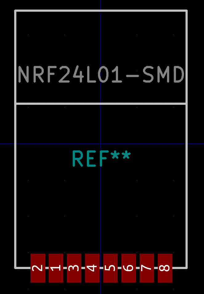
master finished sending; successes=16, failures=0Interesting info: I had so much trouble finding a KiCad symbol and footprint for this device that I started to build my own. But then I found one by accident in the mysensors repo. Important note: Pay attention to the symbol on this one. The symbol as provided in mysensors has VCC on pin 2 and GND on pin 1, but the units I received have VCC on pin 1 and GND on pin 2. I suspect that’s the reason for one review of the unit I ordered stating that the pinout was nonstandard. I don’t know what’s official and standard, but the pinout on the units I received match the photo above, so maybe mysensors is wrong, or maybe there is no standard. Just be aware so that you don’t smoke your transceivers.
Update: LOL. I take it back about the pin 1 vs 2 confusion. Look what they did in the footprint!