

I finally picked up one of those 8x8x8 LED cube matrix kits. I’m a sucker for blinkyshit, all the DC540 regulars know that. I’m doing the rare thing here in documenting before the resolution of all of the issues, just because the processes deserve documentation, I think.
I am by no means a hardware expert. I stand on the shoulders of the entire internet when it comes to mucking about with programming microcontrollers. I’ve gotten better, but it’s still not innate to me the way other aspects of technology are. There are just too many microcontrollers, and too many ways of poking at them. I2C, SPI, JTAG, sometimes it seems almost overwhelming.
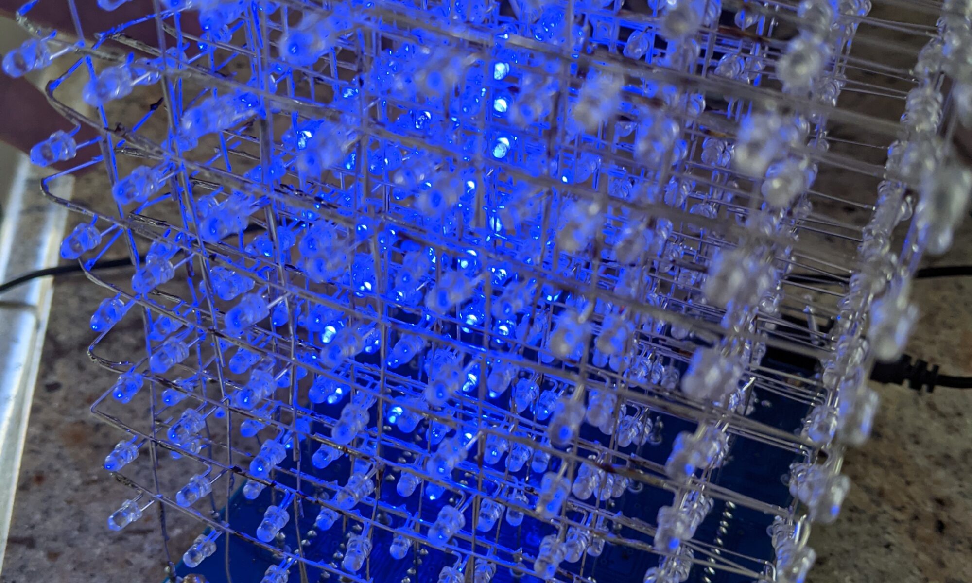
But here we are, with this STC12CA60S2 microcontroller, already installed on the PCB. I went through all the steps over the weekend of soldering all 512 LEDs and the other chips and small parts. I don’t know about you, but when I get close to the end of a project like this, the anticipation starts to really kick in. If I’m not careful, it’s easy to get sloppy and make a stupid mistake. But I didn’t, this time. I did find myself short on LEDs. The kit came with extras of most of the small parts, but inexplicably, only the exact number of LEDs, and two of them were DOA. So I had to order replacements from another supplier, and I didn’t think to order long-leg LEDs for the replacements, so I really had to work a bit to fit them in.
So here we are, it’s all assembled, looks great from a distance, but up close you can see my sloppy skills. This is how the Captcha protections should work, they should evaluate us on our assembly skills. Clearly I am not a robot.
From the instructions I found, the STC12 is supposed to be pre-programmed, and I should just be able to apply power and see the animations. No such luck. It illuminates a block of LEDs, but no animation. To be thorough, I double-checked all the chip orientations, and double-checked all LED paths by using my bench power supply and applying 3V to each power vertical and grounding each ground horizontal to confirm that every LED is “addressable.” I suspect from Internet research that they lapsed and sent me an un-programmed STC12, because it’s documented that this happens. Not a problem, I’m up for the challenge, I’ll figure this out.
Let’s see. It wants a UART USB TTL serial device. Four-pin header. VCC, GND, P30 (RX) and P31 (TX). Well, I don’t have the Adafruit programmer they recommend, but I do have a FTDI FT232R. Let’s give that a shot… Nope, it doesn’t seem to recognize the power cycle, it stays on “Waiting for MCU…” even though I cycled power. NOTE: during this process, the devices is powered, 5V, by the USB programmer. Interestingly, and the Internet backs me up on this, the power light remains dimly lit even with the power button off. Several sources report that parasitic power leaking from the TX line can interfere with the power cycle reset process, preventing this from working. It’s possible this is only an issue on these FTDI programmers, and maybe the problem will go away when I use the recommended Adafruit programmer, which arrives today.
But I’m impatient, I WANT IT NOW! So I started scouring the lab to see if I have any other options available to me. Hmm, I have a Bus Pirate, the Swiss army knife of microcontroller programmers. I spent about an hour last night learning it and futzing with it. The Bus Pirate is interesting but cumbersome. You plug it in, then you serial directly to it (I use screen on the Macbook) and configure it for the purpose intended using a manu system. Then I exit screen and do what I would normally do with a dedicated programmer.
The Bus Pirate doesn’t seem to handle the power situation correctly either, but in a different way. It doesn’t seem to know how to power cycle correctly in UART mode. Even if I set power on before running the stcgal command, it shuts power off when I initiate the sequence and never turns it back on again. What if I disconnect power and ground from the programmer to the board and use the cube’s external power supply? I’ll try that after this post, but I don’t have a lot of hope. I tried this tactic with the FTDI and didn’t see any difference. I wonder if part of the process is the programmer detecting voltage via the same pins it provides voltage on. UPDATE: Tried that on the Bus Pirate, no luck. Also tried another suggestion, putting a 10K resistor inline with TX to keep that parasitic power at bay. No luck. Hopefully the Arduino programmer will work.
Another option is that I have one of those ZIF-socket chip programmers. That’ll be a last resort. I prefer not to pull chips off the board, even though they’re socketed, because of the potential for excessive bending and possible breakage of the pins.
Oh well, one way or another I’ll update this already-too-long shitpost later today. I’ve got at least two paths left to explore today.