I wanted to take a moment to give a little guidance to all of our new followers now that Defcon is over and everyone is resting before catching up on everything. Our twitter followers tripled in the past 28 days, and I realized new followers are coming from all sorts of different angles.
Hi. I’m Baab, sometimes Baabalicious, sometimes just Bob, and sometimes just DC540. I put out feelers for starting this group three years ago. Immediately lured in some quality people who brought intelligence, passion, curiosity and out-of-the-box thinking. The collaboration has been beneficial for all of us, I like to think.
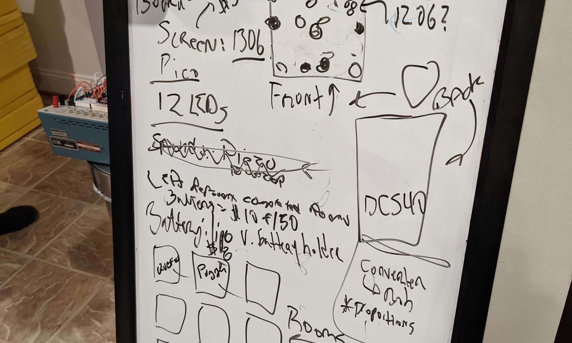
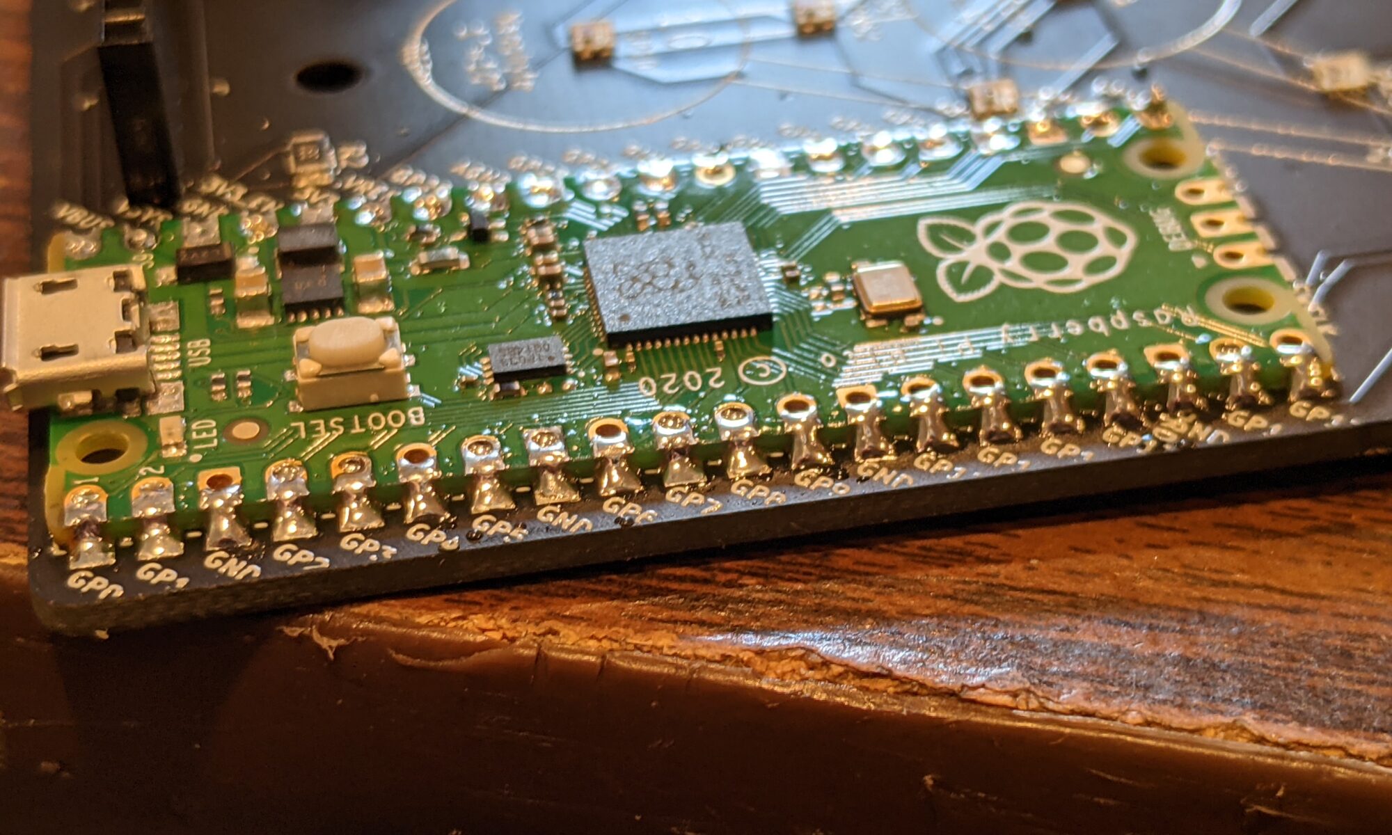
We got the idea for doing a badge probably after DC27. We kind of faded in energy when DC28 was announced as all-virtual, so the badge idea just dragged along. But as DC29 approached and it became clear there would be an in-person component, we became energized again. On May 24, 2021 (yes, just over ten weeks before Defcon opened, we had a planning meeting, wherein we attempted to nail down specifics. The whiteboard at that meeting is attached to this post. We had wanted it themed for Hitchhiker’s Guide, but none of us came up with a structure or shape that really called out to us or that we found compelling, so it was still feeling a bit in question. After everything went home that evening, I sat down to do some reading and kind of had an epiphany.
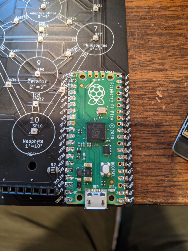
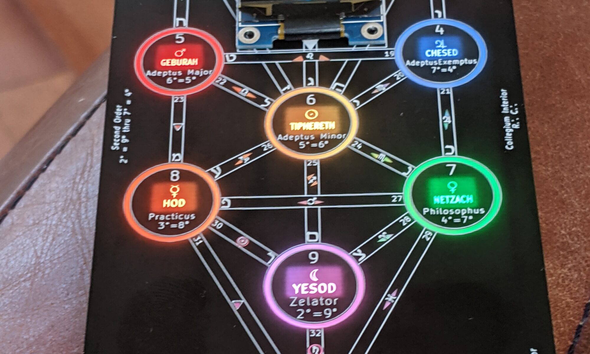
I realized that the general shape we had settled on, which I was already uncomfortable with just because it didn’t holler “pick me” when I looked at it with my mind’s eye, seemed as if it would perfectly accommodate a Tree of Life arrangement. This made me nervous. I was well aware that some of the members of the group may have come from a religious background that might lead them to feel uncomfortable around such symbolism. So I tended to tread lightly when approaching the group with this idea. I came up with some mockups, and either they were too busy to respond or I can be ridiculously persuasive at times, because I got no pushback, and continued to develop. As usually happens with this type of group project or volunteer/nonprofit organization, the person with the most forward momentum tends to get what he or she wants. At a certain point it had gathered so much momentum that it had to be completed.
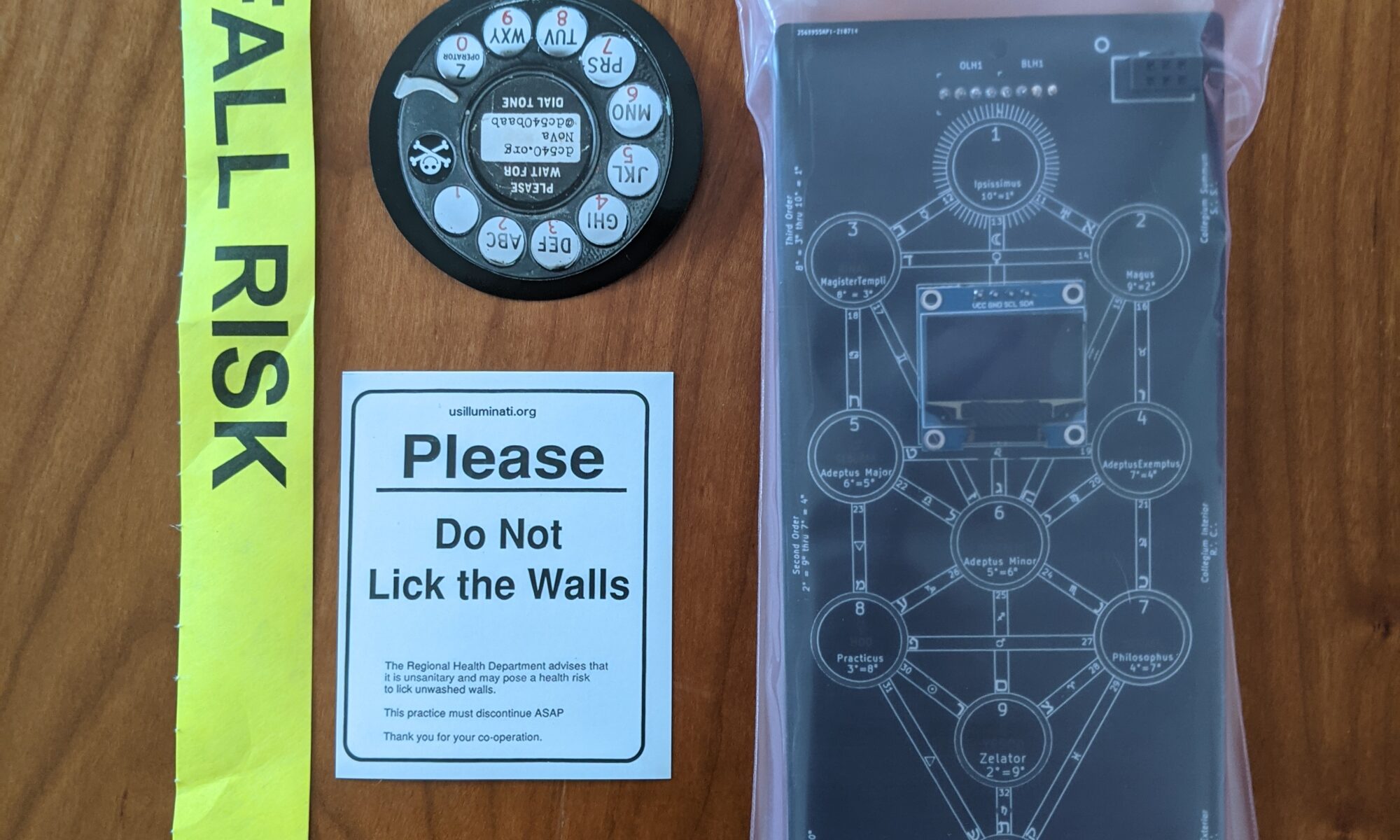
And here we are. We have presented to the Defcon community an esoteric artifact, on behalf of a group who mostly has no historical involvement or investment in such esoterica. And it’s been remarkably well-received. It led to a lot of interesting doors being opened at the con, and some great conversations. I suspect the acquirers had varying reasons for desiring this badge. Some because the backlit presentation with a black solder mask created an especially appealing aesthetic; some because they appreciate anything esoteric; some because they gotta have ’em all, and some, well, who had spend considerable portions of their lives in the study of the badge’s subject matter.
What is Kabbalah? Well, it’s a lot of things to a lot of people. And it’s not the same to all of them. The way I like to describe it to people with no background at all is, “It’s a framework for interpreting the world around you.” In Judaism (I’m not Jewish), it’s been around for hundreds of years. It has been adapted by others, probably most notably Aleister Crowley, and you’ve probably noticed it associated with celebrities like Madonna. It’s not my role to attempt to give you a definitive answer, that would take a whole new website, or maybe a whole new career. But if you gave me enough money, I would try. 🙂
I think maybe I was initially attracted because, you know, spooky occult. But I came back to it from a pure hacker standpoint. It’s like when my family bought a sailboat eight years ago. As a hacker, if you love boats, you will love sailing. It’s a hobby where you can learn something new every day you do it. There are lots of techniques, strategies and optimizations to geek out on. Same with Kabbalah. No matter which angle you approach it from, there is an endless amount of knowledge and information behind it. I met several people during con who have studied it for decades.
I will say this. Based on my own personal research, a fantastic and humorous introduction to Kabbalah, also known as the Tree of Life, can be found in The Chicken Qabalah of Rabbi Lamed Ben Clifford: Dilettante’s Guide to What You Do and Do Not Need to Know to Become a Qabalist by Lon Milo DuQuette. (affiliate link) At the very least, this book should give you an idea of whether Kabbalah (also spelled a bunch of different ways, blame Hebrew ambiguity) is something you’d be interested in studying.
How does this connect with, and why does it resonate with, the Hacker community? This question came up during a talk I was invited to participate in during Defcon. (It was a private talk, don’t get your FOMO in a bunch). I think it was actually during that talk that it sunk in, and I mentioned it, that I think the seeds of this interest were planted in the textfile BBSes many of us frequented back in the day. Who remembers “The Occult Technology of Power?” Every textfiles BBS had subcategories. Hardware, phone phreaking, piracy, occult, basically everything us hacker kids felt was suppressed knowledge. So maybe some of us dabbled back then. Maybe some of us deep dived. Either way, here we are.
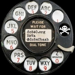
Going forward. As I mentioned before, the members of this group come from different religious backgrounds, and it’s not fair to them to attach any prejudices associated with this badge to them, so going forward, I’d like to separate this out a bit. This might go even farther in the future, but for now, the official DC540 website (dc540.org) and Twitter (@dc540_nova) will focus on the badge hardware, functionality, software updates, and the game we released. P.S., nobody has won yet!
For deeper conversations on esoteric or related matters, to exchange related resources or suggestions, or to continue friendships made at Defcon, or to get random shitposts now and then, hit me up on my personal account (@dc540baab). I met some very interesting people at Defcon, both badge-related and not so much, and I’d love to the continue the conversations. The general rule is, if it relates to something the group gets behind, it’ll go here. If it’s something I think might be controversial to the group, it goes to my personal. I don’t want to scare new group members away with what are essentially personal pursuits.
OK, enough of my too-long-for-twitter babblings the day after returning from Con.