Fun with the Pico and C

When I finally got my hands on some Pico microcontrollers, I was excited to see what they could do. But I was used to the Arduino infrastructure and wanted to explore the Pico on its own terms.

Obviously MicroPython is the easy choice. Once the Pico is flashed with MicroPython firmware, you can write your code in Thonny and just save it straight to the Pico from within Thonny. Easy peazy.

Coding in C requires a bit more effort, especially at the start. You need to get the compiler installed, which varies by OS, and since I develop on a Mac with the M1 Silicon chip, it’s even more obscure for me. Fortunately, it’s all right there in the docs. Specifically, the “Getting Started” document, chapter 9, page 37. An architecture flag allowed the brew command to work, and I was off to the races.

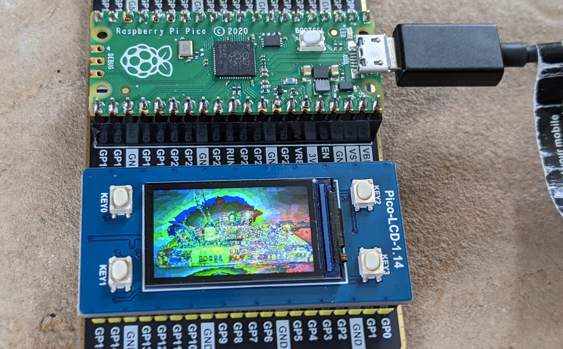
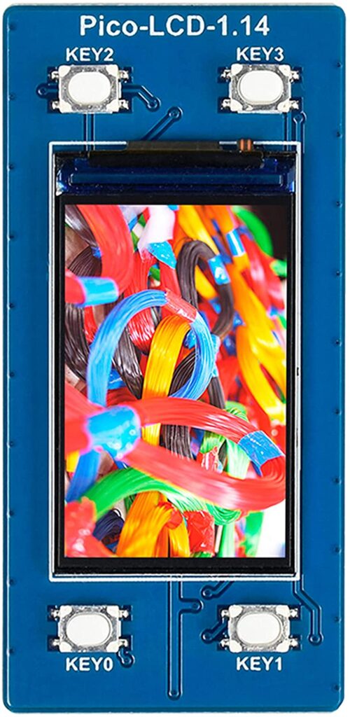
Pin stuff is easy. I know I can do that. I wanted to skip to some wacky complicated stuff. So I started with the Waveshare demo for the Waveshare Pico-LCD-1.14 display hat with buttons. I decided i wanted to modify that demo to display my own image instead of the stock image. After some trial and error, I was sort of able to do so.

The image is stored as a c hex array. Getting that file exactly right was time-consuming. I didn’t see an image converter in their examples arsenal, so I found this one online. By tweaking the settings a bit I was able to get an image to display .. sort of. The color mappings are different somehow. Maybe 65K colors isn’t that many after all. I’ll have to mess with it with a more legible photo.

Original photo for reference:

The display is 240×135 and 65K colors. I’ll update this post when I figure out more. This is just to make it a little bit easier for those who want to get into C programming on the Pico but don’t know where to start.

Also, these kids will show you the general build environment / compile process completely if you live in Ubuntu-land. Amazing.

Prepping for 2021’s first in-person meetup

Next week’s meetup is slated to be DC540’s first in-person meetup this year. We decided to schedule the in-person meetup in the backyard. Since we made that decision, the CDC advised that vaccinated people should be able to gather indoors maskless. But we’re fine with outdoors. Especially since, when we scheduled it, it was looking like it might rain Monday evening, but since then the probability has decreased steadily. Looking very promising now.

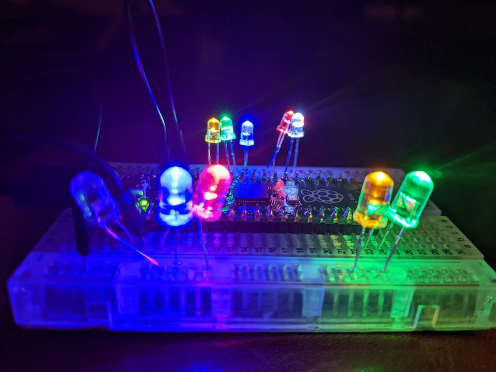
We’ll have enough Raspberry Pi Pico microcontrollers to go around, I’m trying to pre-solder a bunch of headers so you don’t have to waste time soldering and you can get started right on deploying programs onto it. I’ll also have some breadboards and LEDs to play with if you’re so inclined. If you want to be prepared to play with that, install Thonny on your laptop and consider bringing a standard MicroUSB cable. MicroPython is WAY easier to get started with on the Pico than C. Plug it in with Thonny running, Thonny will prompt you to flash MicroPython firmware onto it, and then you can just save your python programs straight to the USB-connected Pico and run them. Easy as Pi.

More fun with Raspberry Pi Pico

Our next meeting will again focus on the Raspberry Pi Pico. We are looking at, weather permitting, an outdoor in-person meeting next Monday. Stay tuned in the Discord to see if it’s happening.

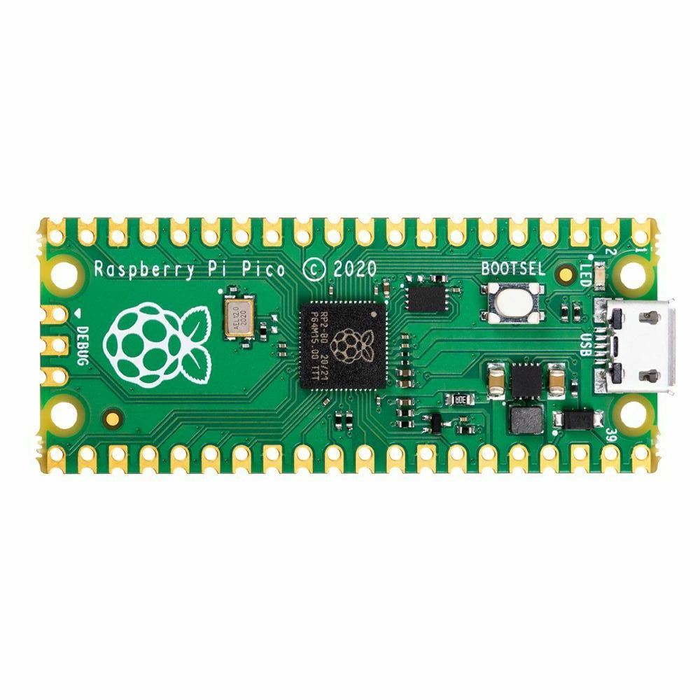
So, our regulars will know that one of our founding members, in a moment of extremely questionable judgment, purchased an entire REEL of Raspberry Pi Pico microcontrollers. If you’re out of the loop on this device, it’s closer to an Arduino than the previous iterations of the Raspberry Pi. While the Raspberry Pi 2, 3, 4 and Zero are all tiny computers onto which you install an operating system, the Raspberry Pi Pico is a microcontroller, onto which you flash firmware and code.

The Pico, as a microcontroller, has a lot of things going for it. It’s very small, it’s light weight, and the castellated edges provide a lot in terms of mounting flexibility. You can either mount it thru-hole or surface-mount it on pads!

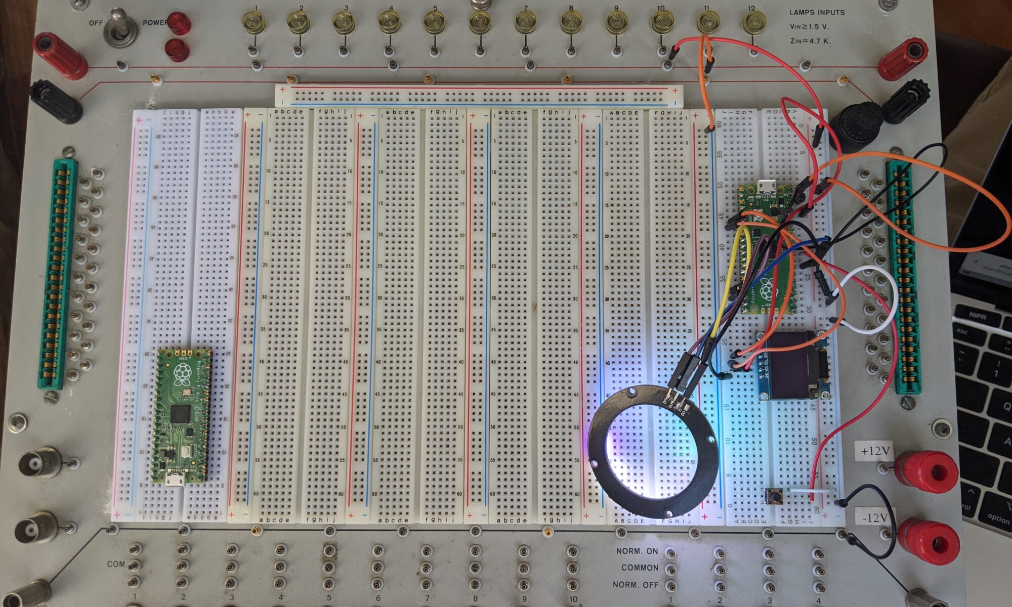
The easiest way to use it is with MicroPython. By flashing the Pico with MicroPython firmware, it provides and environment that allows you to very easily drop new MicroPython programs onto the Pico just by pressing the boot button and having it mount to your computer as a storage device — programs that can easily interact with LEDs, sensors, servos, etc… basically anything that a microcontroller can do by sending and receiving data on its I/O pins, this little baby can do. See the recent post on the vintage powered breadboard for an example of the Pico in action.

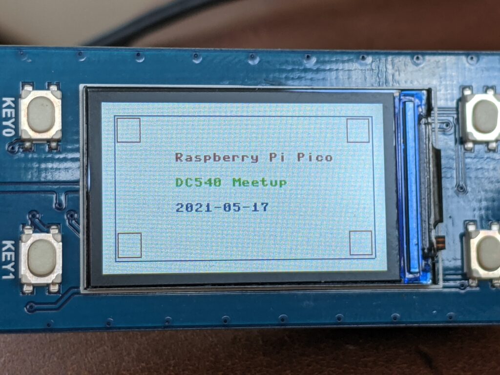
This also includes using tiny OLED displays. For example, the Waveshare 1.14″ display for Pico — this is available in a “hat” format, meaning it sits right on top of the Pico once the headers are installed in the correct direction. At that point you can easily build a 3d-printed housing for it or include it in a larger project’s design. It conveniently includes four buttons to drive any menus you come up with or provide some other sort of input.

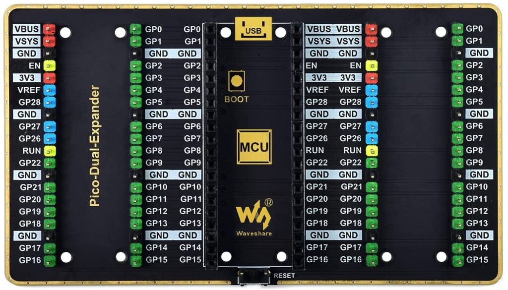
Then there’s the GPIO expander, also by Waveshare. It’s a single board, on which you mount the Pico, and it splits all of your GPIO pins into left and right versions. So if you have two different devices you want to connect (and there are no conflicting pins), it’s pretty easy to do that.

If you were around a few weeks ago, our man Kevin provided a really cool demo of reverse engineering using the Pico.

If the weather holds out, our next meeting maybe in person, outdoors, and we’ll have some cool Pico stuff to demo, build, and play with.

LED 8x8x8 Matrix: I’m Very Confused

If you followed my previous post, you’ll know that I’ve been battling with one of those $20 LED 8x8x8 matrix kits recently. It was very frustrating, there’s little support out there and confusing information, and when you’re in that state you start to doubt yourself and assume you must have done something wrong. But I tested everything I could possibly test and I was convinced I did everything right.

At that point, all signs pointed to a chip that needed programming, and I tried with numerous sets of instructions and at least four separate programming adapters. Nothing was working, and the display stayed in its broken state.

I came up with two final plans. First, I would buy a new 12C5A60S2 IC, and see if that one would program correctly using the various adapters I have. Failing that, I would fork over the $20 for an entire new kit, build the base and test it extensively before attaching the LED faces to it.

The replacement chip was $5 shipped, so I pulled the trigger and waited. The chip arrived last night, but I wasn’t motivated last night, so I hit it first thing this morning.

Keep in mind, this is a “new” chip, allegedly.

I pried out the old chip, and carefully inserted the new one into the socket. I powered the unit up, thinking I’d spin around in my chair to access the programming interface (I’m using a Pi4 with the USB programming interface because linux supports the drivers natively). Imagine my surprise when the animations start scrolling on the LEDs.

What the everloving fuck? I bought what I thought was a brand new chip, assuming I would have to program it. Only to install it and discover it already has the animation firmware I need for my project?

Best as I can guess, this project is by far the most popular reason for people having these chips, and either it’s a return that someone programmed, or they preprogram all of them as a burn-in test. I might actually have to follow up with the ebay seller, because this has broken my brain.

Anyhow, I’m glad it’s finally working.

Analog Archaeology: Elite 3 Circuit Design Test System

A few weeks ago, I came across this vintage powered protoboard system on FB Marketplace. It seemed to be priced reasonably for its functionality, and the owner stated that it was working. So I snagged it. I admit I was tired of working with individual breadboard strips and cheap chinese power supplies, and wanted something larger and more stable. The fact that this provides 12V and 5V and a number of lamps, switches and buttons made it much more attractive.

I started looking online for a manual for it. It’s not a complicated unit, but I wanted to know what the manufacture intended for use case and workflow. So far I have been unable to find much on it other than a brochure on archive.org and a YouTube video from “IMSAI Guy” who picked one up for free at a junk drop-off location in Santa Clara. IMSAI Guy’s video was extremely helpful, as it gave me some clues about usage and expectations. Much of the board is unlabeled, but fairly intuitive. +12V and -12V terminals on the lower right, and two bare GND terminals near the bottom of the unit, are the only terminals that are labeled.

On the video, IMSAI guy shows two pairs of red terminals near the top, one on the left side and one on the right, and it sounded like he was saying that they are 5V terminals tied together. Here’s where mine starts to differ. Rather than two pairs of red, I have two red/black pairs. I powered it up and grabbed the multimeter. Measuring from red to ground gives the expected 5V. Black to ground gives zero. Is this another ground? Hmmm not quite. Red to black gives 4.7V. At this point I’m a bit confused. It’s definitely the same model as in the video, but it’s different.

So I went through and tested the other features. All twelve of the lamps are functional and pre-grounded with a 4.7K resistor inline, all you need to do is tie them to power >1.5V and they light up. The ten switches are nicely configured, they provide patch points for normal on and normal off. Same with the four momentary button switches.

There are edge PCB connectors on each side which I can’t imagine using at this point in time, and a pair of BNC jacks on the left side. Those could be interesting.

So I built a couple of Raspberry Pi Pico example circuits and powered them up, just for the photo op, and to put the thing through its paces.

But I was still perplexed about the black terminals. Why does mine have different terminals than IMSAI Guy’s? I made a mental note to open it up later and figure this out.

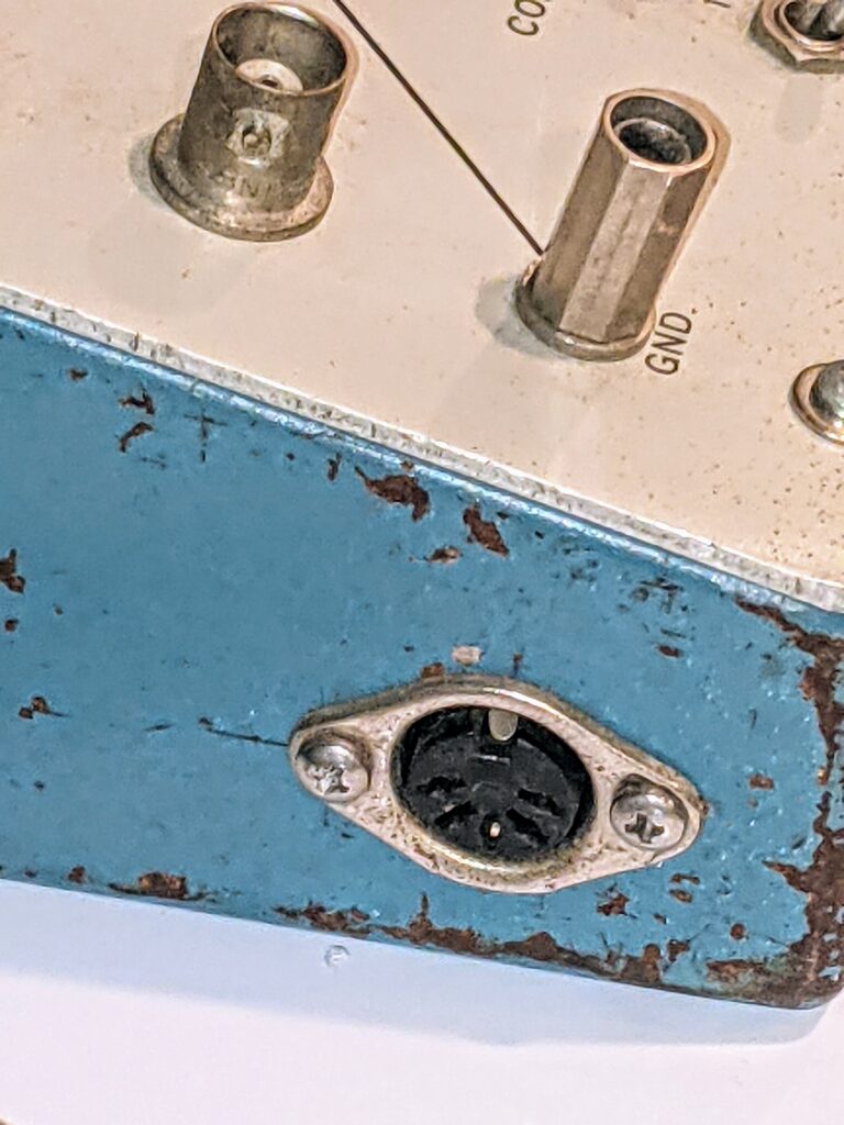
Then last night I looked at it from a different angle and noticed something I hadn’t seen before. There’s a DIN-5 connector on the left face of the unit that I hadn’t noticed before. What possible use for a DIN-5 connector would this thing have? I opened up IMSAI guy’s video again, and watched as he spun the unit. Nope, I don’t think his has this. Now I HAVE to open it up.

WOW. So mine is a modified unit. Getting the docs probably wouldn’t help at this point, unless this is a later model and how it was released by the manufacturer. (shrug).

I found another expired auction listing for one of these, and it did NOT have the DIN-5. So either it’s not stock or it’s a later model.

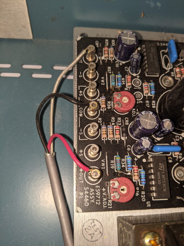
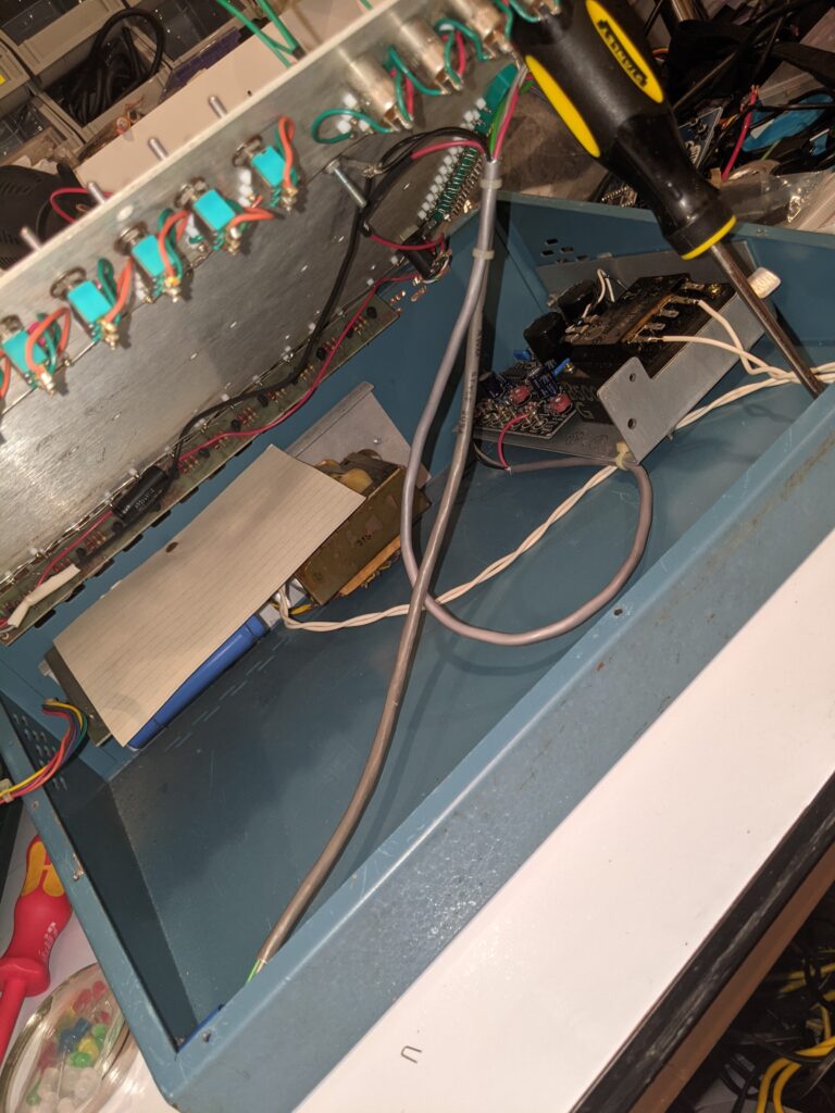
Opening up the unit, I find another board that’s not on the other two examples I’ve found. Over to the right is a more modern power supply than the brick transformer it came with. An E59712 board. And now the light bulb in my head goes on. Maybe, since this board seems to have adjustable voltage at R21, maybe it’s feeding the black terminals somehow, providing an alternative to just +/-12V or +5V. Further research required.

Add to that the fact that this subassembly is tied to the main power supply, the DIN-5 connector AND the surface board, and I’m starting to get a picture of things. I’m going to have to test more, but I feel like either this is a supplemental board designed to give more flexibility to the unit, or the main power supply died and this is a more modern replacement that was shoved in. I really am curious about the DIN-5 use case, though.

Mine had a SUNY asset tag on it, in case you’re curious. Anyhow, more digging later.

Update: Here’s a PDF of the original brochure. Not as good as a manual, but useful just the same.

Bashbunny — still fun in 2021? (part 1)

I decided to dust off my Hak5 field kit and refamiliarize myself with all the tools. I have the bashbunny, the LAN turtle, the rubber ducky, and a bunch of utility adapters. I also have a wifi cactus in there, but I’m pretty sure I picked that up separately.

I started with the Bashbunny, since it’s so versatile. I won’t address advanced topics like locked PCs in this post, this is very basic bashbunny talk. So the scope here is “some dumbass left me unmonitored access to a PC.” Either unattended, or “here, you drive while I go get a drink.” Yeah, don’t do that with someone who might have these tools and tendencies.

So the first thing I noticed was that it was out of date. Fortunately, Hak5 has very usable instructions and tools for making it current.

So I went through all that process, bringing my payloads and firmware up to current levels. It was a fun exercise.

The first script I ran was recon/MacProfiler. I set the Bashbunny to Arm, copied the payload.txt into switch1/, ejected it, switched the Bashbunny to position 1, and reinserted it.

Ran once, and it left the bashbunny mounted. The second time I ran it, it successfully ejected itself, which is important if you’re trying to be a bit stealthy. At some point I’ll investigate that further.

It worked well. It gathered a list of all of the /Applications on my MacBook Air, a list of all users, and all the networking information I might need. Oh, and a list of things that startup automatically. All of this is tremendously useful for recon, so that you can craft a later attack for next time you have access to the same PC.

Next, I tried macinfograbber. Similar concept, but it’s specifically crafted to grab a copy of any spreadsheets (xls/xlsx) in the user’s Documents directory. By extension, of course, this could mean whatever type of files you’re specifically aiming for.

(arm) (eject) (switch) (reinsert)

OK, this did some stuff, then ended with a red LED indicator on the bashbunny. This translates to “no files found” according to the script. Kind of surprising. Do I really have no xls/xlsx files in my Documents directory? Let’s see… Hmmm, yep. I do. Why did it fail? At first I thought maybe it was spaces in the filename and a poorly-written script, but I renamed it to a single word and tried again and it continued to fail.

So I dug deeper. Here’s the command that macinfograbber uses to grab those files:

cp ~/Documents/{*.xlsx,*.xls,*.pdf}  /Volumes/BashBunny/loot/MacLoot/xlsx/

And here’s the problem. I’m assuming these scripts were written back in 2017 when the Bashbunny was fresh. In 2019, Apple switched from bash to zsh on the Macs. And apparently, zsh fails this command if any glob fails for safety reasons. So that line will need to be rewritten, or just broken out into individual commands.

More on the Bashbunny later. I plan to dig deep through the whole payload library for a 2021 refresh, because it’s still useful. Although you might want to remember to take your USB-C adapter with you for modern MacBooks. 🙂

CPanel’s “Plus Addressing” feature is specifically weird and problematic.

I got off on a tangent recently, wanting Gitlab’s “Service Desk” functionality to work. This feature allows remote users to open issues via a crafted “Plus addressing” email address, i.e. gitlabaddress+gitlab-project-identifier@yourdomain.com. I did everything I was told to, and was struggling with why it wasn’t working. It just wasn’t detecting new emails at all.

So I logged into the webmail of the domain on which I had set up the email account, it’s a cPanel website by one of the big commodity shared hosting providers. Sure enough, nothing is in the inbox. Hmm. Maybe Plus Addressing isn’t as ubiquitous as I thought. I mean it’s been a thing with Gmail for a while now, but maybe…

Nope, research showed that cPanel has indeed adopted it.

But wait. Ooooooh, cPanel, you think you’re crafty, don’t you? Rather than just allow the email in and rely on the user to filter it, cPanel actually immediately routes the email to a folder named for whatever you throw in after the plus sign. If the folder doesn’t exist, it just creates one. That’s sure convenient! Except for one thing — the user has no way of knowing that folder exists, at least via webmail, because the user is not “subscribed” to new folders by default. The only way I was able to find the emails is to go into “Manage Folders”, then they show up in the folder list, with “subscribed” unchecked. So I subscribed, then viewed the emails, then dragged them into the inbox, where they were promptly picked up by Gitlab.

A unique problem that may require a unique solution… I’ll have to think on this one a bit. Ideally, I would want these emails to enter the inbox normally. I know they think they’re doing the right thing for users wanting to use this as a spam filtering mechanism, but by having different behavior than other vendors supporting the extension of email address with a plus sign, they have created a dilemma for vendors who choose to make use of this functionality in their features.

Tested also on my Thunderbird client. Sending to a nonexistent folder hides the message in a newly-created unsubscribed folder. No hint to the user that it exists. Sending to an existing folder adds a new unread message to that folder.

So you can put things into a recipients mailbox without anyone knowing they are there…
You can take up SPACE in a recipient’s mailbox, causing a denial of service, without them knowing why unless they go out of their way to look for unsubscribed folders. What if I sent 10,000 emails to that newly-created unsubscribed folders. Or even more annoying, 10,000 randomly-created folder names.

Fascinating.

Fixing a broken Defcoin mining pool; a saga

Follow along in my journey of fixing a broken NOMP/MPOS Defcoin mining pool. It wasn’t a public pool, it was my own personal solo mining pool. The idea was that it would eventually become public, but you know how it is, sometimes it takes time to get around to doing things. Doing something for me is easy, doing it for public requires much more careful thought and planning.

Careful thought and planning that I wasn’t executing last year, sometime between February and April, when I haphazardly ran an apt upgrade on the Ubuntu 18.04 VM that was running my pool. I didn’t think anything of it. It was a busy time. I was in Vegas for a while in February, then I came home and went to BSides Nova, then the world shut down and mining Defcoin was just not on my mind.

I noticed that my wallet wasn’t getting fatter, so I logged in to take a look, and realized it was 100% out of space. The shares table was 3GB. It wasn’t important at the time, so I abandoned it in place.

Cut to this week, when bashNinja and others are talking about doing some work on Defcoin. Pools are popping up, people are getting excited again, there’s talk of forks, and I’m right there paying attention, because sure, I want my pool up and running again. But man, I’m not looking forward to figuring out this software made of black magic and rickety scaffolding and held together with government cheese. I barely got it running the first time, I clearly didn’t understand it.

So, reluctantly, I started digging. First, my defcoin core wallet is not talking to any peers. It only has one peer address and it can’t connect. Well, it has been a year. I asked on bashninja’s discord about that, and got a quick and easy response. I was pointed to a post in /r/defcoin that contained a list of peers that can be manually added via the defcoin-qt debug console window. Once I did that, it started to talk to peers again, and began to wriggle its way towards 2021 on its own time.

Second, the shares table. Nothing can work with that table in that state, everything’s just running too damn slow. 17 million rows. So…

Let’s clear that table. At this point I have no idea whether it will prevent the rest of the system from working. [Keep in mind that I never gained a full understanding of how the system is strung together, I just got it working and let it go. So at this point, I’m reverse engineering something I slapped together myself.] But in case I need it, I’ll back it up. So… create table shares_manual_backup like shares; insert into shares_manual_backup select * from shares; Then, once I confirmed everything copied, delete every row from shares. This allowed me to navigate, and allowed the WebGUI to respond again. I needed that, there’s valuable troubleshooting info hiding in there.

So browsing around the GUI, I see that all the cron jobs have been disabled. It took me a while to remember where to find and fix that. I don’t know why an interface wasn’t created for it. How it works, I learned, is that if one of the cron jobs and their subtasks fail, they update or add a row in the monitoring table to indicate that the job is disabled, then they no longer run from cron, forcing the administrator to address the underlying issue before it gets worse.

I tried enabling them and running them, they just revert back to disabled. So I dug around to find where MPOS logs results of those cron jobs, and I found them. /home/(username)/mpos/logs/(jobname)/log_(date)etc. I found very strange results in those log files. Problems with scripts that I hadn’t changed. Curiouser and curiouser.

So again this took a while, but eventually I happened up on a clue. A script failing because a command had been deprecated in PHP 8. So now it’s starting to dawn on me that my update might have caused this. Also, it’s having trouble finding memcached, which I know is installed. I don’t quite understand, until…

OK, I’ll add a phpinfo file to the public-facing web area of MPOS. Go to it. Sure enough, no memcached. But wait. This says we’re running PHP 7.3. How can this be? Back to command-line. php -v shows PHP 8.0. What is this trickery??? OK. Since the problem is clearly in the command-line, because the cron jobs are failing, let’s try backing this version down to PHP 7.3. This can be done with update-alternatives.

That worked. Now we’re getting different errors.

021-04-14 18:53:49 - ERROR --> Failed to update share ID in database for block 1273177: SQL Query failed: 2006
2021-04-14 18:53:49 - ERROR --> Failed to update worker ID in database for block 1273177: SQL Query failed: 2006
2021-04-14 18:53:49 - ERROR --> Failed to update share count in database for block 1273177: SQL Query failed: 2006
2021-04-14 18:53:49 - CRIT --> E0005: Unable to fetch blocks upstream share, aborted:Unable to find valid upstream share for block: 1273178
2021-04-14 18:53:49 - INFO --> |    23103 |    1273178 |           24.75 |            |                           | []              |                 |          any_share |
2021-04-14 18:53:49 - ERROR --> Failed to update share ID in database for block 1273178: SQL Query failed: 2006
2021-04-14 18:53:49 - ERROR --> Failed to update worker ID in database for block 1273178: SQL Query failed: 2006
2021-04-14 18:53:49 - ERROR --> Failed to update share count in database for block 1273178: SQL Query failed: 2006

OK, this makes sense. Of course it can’t associate share IDs with blocks, I’ve wiped out the share table! So let’s look closer at the share table, because I’m really hesitant to dump 17 million records back in. Looking closer at the data, the way it associates a share ID with a block is the “solution” field in the shares table, which maps to the “blockhash” field in the blocks table. A couple of quick count queries reveal that of the 17 million records in the shares table, currently relocated, fewer than 7,000 contain a populated solutions field. Those are the shares that resulted in a blockhash. So, on a hunch, I select just those rows back into shares and run the findblocks command again. Lo and behold, it’s not failing. It’s taking its time, though. About two seconds for every three records. So roughly this “fix,” assuming it works, will take a while.

I let it run for a while, and then I tentatively give the pps-payout script a poke, since that’s another one that was failing instantly because it wasn’t finding any shares that matched its criteria. Sure enough, it’s able to chew on the data that findblocks is now fixing. Good.

So the way the scripts are re-enabled is, you fix the underlying problem, then run the script with the -f argument. If it succeeds, it re-enables the cron job. So it’s important to check that, because any problem can cause a cascade of further problems that eventually kill the system.

I probably won’t know until midnight tonight whether I’m finished with my NOMP/MPOS deep dive, but I will sleep well knowing that I’ve taken it far from the broken state it was in, and I’ve learned a lot along the way. Oh, and I documented everything I found in my personal Gitlab issues and Wiki for the project, so even if I unlearn it, it’ll be less painful next time.
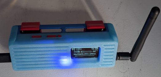
Illuminated Latching Switches on a budget

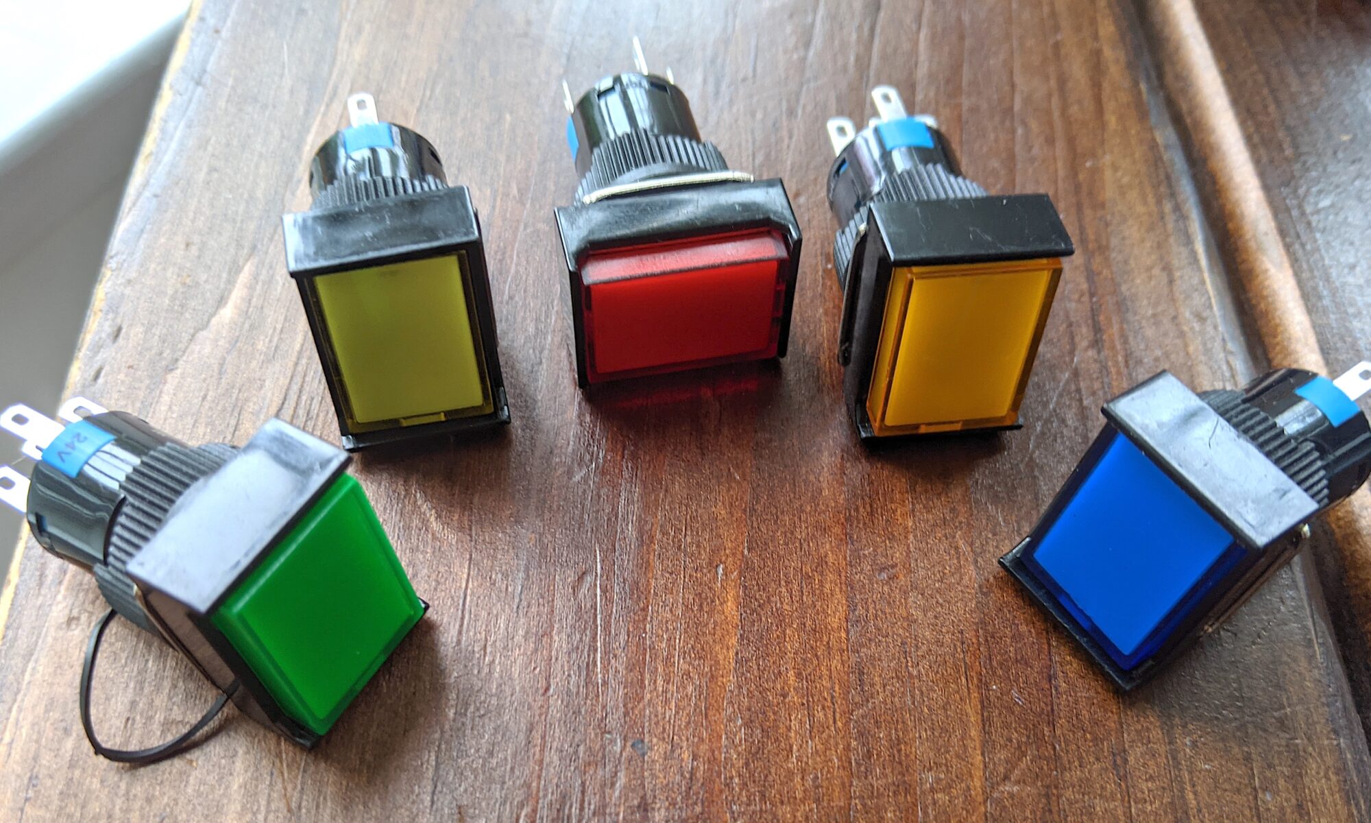
When I first saw this DIY Raspberry Pi Cyberdeck, I knew I wanted to build it. I love the aesthetic, and I already have most of the parts. Element14 was kind enough to present most of what I need via direct links.

And then I saw the price. Those beautiful rectangular switches to the right of the screen? Illuminated latching switches, $20 each! I just can’t stomach blowing $100 on switches for a DIY case.

So I started shopping. And damned if I didn’t find them ALL quite pricy. I must have shopped for over a week in my spare time, and really couldn’t catch a break.

Until I found these:

Amazon. $10.89 for five, around half the cost of ONE everywhere else. Ordered March 25, shipped from China, arrived today. Not bad for China.

Wish me luck.

Two Gitlab books briefly reviewed

If you’re following along like a good little do-bee, you’re already aware that i’ve been evaluating Gitlab as a functional equivalent to (much of) my Atlassian infrastructure, due to unforeseen events I will no longer vent about.

This required me to actually LEARN gitlab in the process.

In my usual fashion, the very first thing I did to start learning it was to install it. In my infrastructure. No planning, no strategy, just follow the install doc and get it up and running so that I can start playing with it.

That alone was so easy that I got cocky. Again, with no planning and just the barest hint of strategy, I integrated it with my FreeIPA ecosystem. No problem.

Then, following the simplest of breadcrumbs, I was able to migrate both my existing Bitbucket infrastructure AND my existing Jira dataset. Some of those subsets of data referenced the same internal projects, so it was fun and informative to sort through that.

So here I am with 92 projects, many with open and closed issues, some with git repositories. Seems good. I’ve already started working through issues and generating new ones.

But now here I am with a mostly unfamiliar new interface. I’ve been around, I’ve used many interfaces and I’m reasonably competent with git, but I have yet to figure out what else Gitlab can do for me to improve my life.

So I picked up The Gitlab Cookbook and Gitlab Repository Management to see if they would expand my knowledge.

They did, to an extent. But neither of them were perfectly suited to my needs. This is my gripe with most of the computer books out there. The widest audience for a book is going to be people who are new to the product, the technology or the paradigm. There are very few books out there that are capable of taking you into the stratosphere — the deep tracks of a product, where hearts and minds are conquered, lives are changed forever, destinies altered…

So yeah. These books covered installation, user management, creating projects and issues, etc. I was able to skim through most of that. The CI/CD sections will probably prove useful at some point, but that’s not exactly where I’m going right now. I guess what I want is all the cool little timesavers that improve our lives and the quality of the data retained and created by these products. Neither of these books really got into that.

As an example, I wonder why neither of these books chose to explore “Quick actions.” This is the kind of deep knowledge I need. When I can open an issue, and type “/spend 1h” in the description box to document the fact that I spent an hour on something, that means a lot to me. When I can type “/shrug” to append ¯\_(ツ)_/¯ to a comment, these are the important things I need to know.

So now I know. I don’t need a Gitlab book. I need a Gitlab Quick Actions Cheat Sheet.

And so do you.

And here it is. https://docs.gitlab.com/ee/user/project/quick_actions.html. You’re welcome.

The rest of Gitlab is mostly pretty intuitive, or else completely dependent on your knowledge and understanding of git itself.

HELP! I’m surrounding myself with plastic!

At a certain point, 3D printing shapes just for fun and novelty takes a back seat to utility.

I’ve been battling the accumulation of AA and AAA batteries for the various remotes, conference badges and other random gadgets in my life. For a while I kept them in an old empty checkbook box, then in a plastic box that once housed resistors, but finally I decided to do something useful and solve the problem.

I printed this lovely thing I found on Thingiverse. It’s much more stable than cardboard, and holds more than the plastic parts bin. No more random batteries rolling off the desk and onto the hardwood floor. Now I feel like I should print another one, in another color maybe — one for fresh alkaline batteries, and a separate dual container for to-be-charged rechargeables.

Total cost of printing, I’m going to guess around $2 worth of PLA plus electricity.

I Refuse to Admit Failure… YET.

I finally picked up one of those 8x8x8 LED cube matrix kits. I’m a sucker for blinkyshit, all the DC540 regulars know that. I’m doing the rare thing here in documenting before the resolution of all of the issues, just because the processes deserve documentation, I think.

I am by no means a hardware expert. I stand on the shoulders of the entire internet when it comes to mucking about with programming microcontrollers. I’ve gotten better, but it’s still not innate to me the way other aspects of technology are. There are just too many microcontrollers, and too many ways of poking at them. I2C, SPI, JTAG, sometimes it seems almost overwhelming.

But here we are, with this STC12CA60S2 microcontroller, already installed on the PCB. I went through all the steps over the weekend of soldering all 512 LEDs and the other chips and small parts. I don’t know about you, but when I get close to the end of a project like this, the anticipation starts to really kick in. If I’m not careful, it’s easy to get sloppy and make a stupid mistake. But I didn’t, this time. I did find myself short on LEDs. The kit came with extras of most of the small parts, but inexplicably, only the exact number of LEDs, and two of them were DOA. So I had to order replacements from another supplier, and I didn’t think to order long-leg LEDs for the replacements, so I really had to work a bit to fit them in.
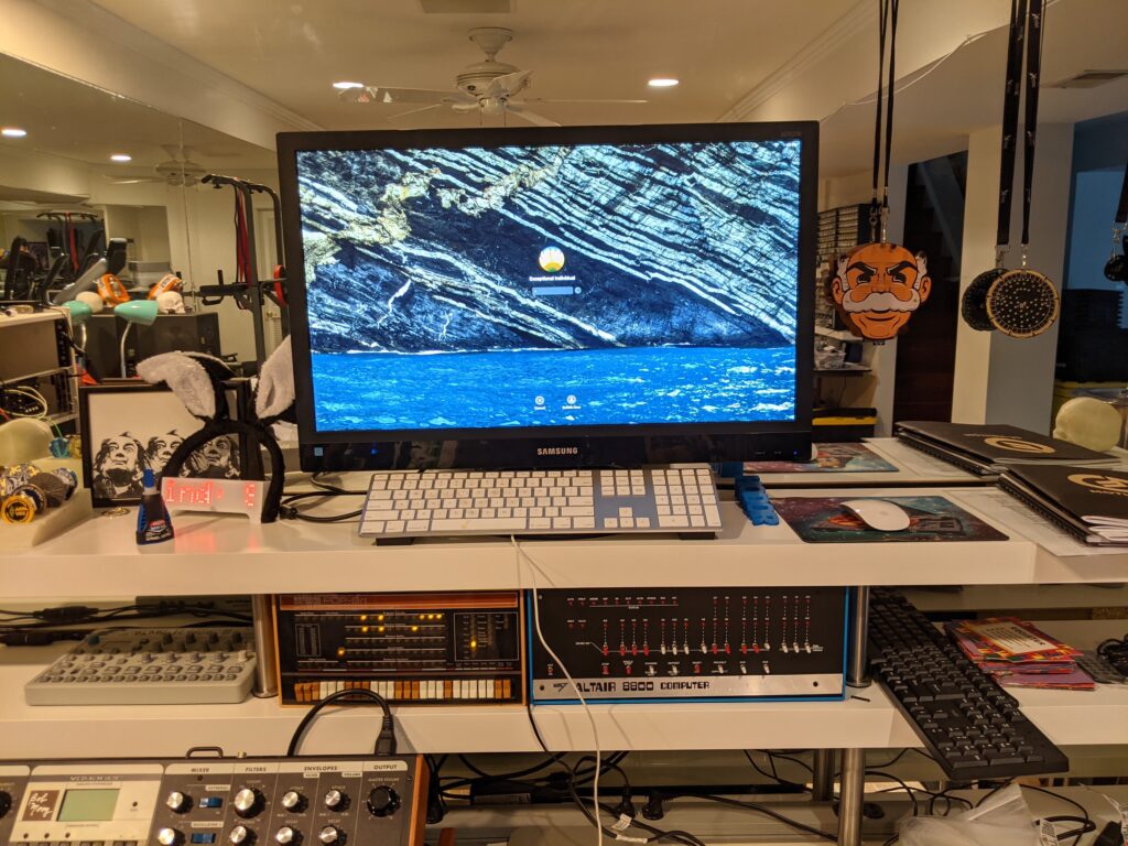
So here we are, it’s all assembled, looks great from a distance, but up close you can see my sloppy skills. This is how the Captcha protections should work, they should evaluate us on our assembly skills. Clearly I am not a robot.

From the instructions I found, the STC12 is supposed to be pre-programmed, and I should just be able to apply power and see the animations. No such luck. It illuminates a block of LEDs, but no animation. To be thorough, I double-checked all the chip orientations, and double-checked all LED paths by using my bench power supply and applying 3V to each power vertical and grounding each ground horizontal to confirm that every LED is “addressable.” I suspect from Internet research that they lapsed and sent me an un-programmed STC12, because it’s documented that this happens. Not a problem, I’m up for the challenge, I’ll figure this out.

Let’s see. It wants a UART USB TTL serial device. Four-pin header. VCC, GND, P30 (RX) and P31 (TX). Well, I don’t have the Adafruit programmer they recommend, but I do have a FTDI FT232R. Let’s give that a shot… Nope, it doesn’t seem to recognize the power cycle, it stays on “Waiting for MCU…” even though I cycled power. NOTE: during this process, the devices is powered, 5V, by the USB programmer. Interestingly, and the Internet backs me up on this, the power light remains dimly lit even with the power button off. Several sources report that parasitic power leaking from the TX line can interfere with the power cycle reset process, preventing this from working. It’s possible this is only an issue on these FTDI programmers, and maybe the problem will go away when I use the recommended Adafruit programmer, which arrives today.

But I’m impatient, I WANT IT NOW! So I started scouring the lab to see if I have any other options available to me. Hmm, I have a Bus Pirate, the Swiss army knife of microcontroller programmers. I spent about an hour last night learning it and futzing with it. The Bus Pirate is interesting but cumbersome. You plug it in, then you serial directly to it (I use screen on the Macbook) and configure it for the purpose intended using a manu system. Then I exit screen and do what I would normally do with a dedicated programmer.

The Bus Pirate doesn’t seem to handle the power situation correctly either, but in a different way. It doesn’t seem to know how to power cycle correctly in UART mode. Even if I set power on before running the stcgal command, it shuts power off when I initiate the sequence and never turns it back on again. What if I disconnect power and ground from the programmer to the board and use the cube’s external power supply? I’ll try that after this post, but I don’t have a lot of hope. I tried this tactic with the FTDI and didn’t see any difference. I wonder if part of the process is the programmer detecting voltage via the same pins it provides voltage on. UPDATE: Tried that on the Bus Pirate, no luck. Also tried another suggestion, putting a 10K resistor inline with TX to keep that parasitic power at bay. No luck. Hopefully the Arduino programmer will work.

Another option is that I have one of those ZIF-socket chip programmers. That’ll be a last resort. I prefer not to pull chips off the board, even though they’re socketed, because of the potential for excessive bending and possible breakage of the pins.

Oh well, one way or another I’ll update this already-too-long shitpost later today. I’ve got at least two paths left to explore today.

Is Gitlab a viable Atlassian alternative? Spoiler: maybe?

Maybe you’re one of those stubborn people like me who insists on self-hosting everything. Maybe it’s a requirement due to sensitivity of data, or maybe it’s just pride. In any case, that’s what I was doing. I was proud of my Atlassian setup. I happily paid my $10 each for 10-user licenses of various Atlassian products. Jira, Confluence, Bitbucket.

Everything was fine, and everyone was living happily ever after.

UNTIL.

And this is where I sacrifice my personality for professionalism. In my humble opinion, Atlassian made a huge error in judgement. They decided to end support for their “Server” line of products in favor of “Cloud” and “Data Center.” No more $10 10-user licenses for self-hosted apps. 10-user licenses are FREE now — in the cloud. You want to host it yourself? Fuck you, go get the Data Center version. How much is it? Well, if you have to ask…

And yes, I was holding back. I’m a little bitter.

So here I am, exploring ways I can take my business elsewhere. I’m a simple man with simple needs. I don’t need all the workflow bells and whistles that Jira offers. Hell, we don’t even use most of that at my job. At the core, I need projects and issues. Gitlab has that. And of course Gitlab can do everything that Bitbucket does. What’s left? Hmm, Confluence. Well, I’ll explore that part later. I do know that there’s a “Markdown Exporter” plugin for Confluence that will export “markdown” documents in a way that can be imported into Gitlab, Github and other apps. I just don’t know what the paradigm equivalent is for it just yet.

So let’s start with eradicating Bitbucket.

OK, I built a VM. CentOS 8. Gitlab’s installation instructions are crystal clear. A few prerequisites, an update, and a repo install, then a package installer. Nice, that’s how I like it. OK, they include a LetsEncrypt cert deployment by default. We’ll have to get rid of that, I have my own CA internally, and I issue certs from that. Done, not so hard. Next, SSO. I have FreeIPA in my infrastructure and had integrated the Atlassian products with that. Can I do that with Gitlab? Shit yeah. Easy as chocolate pie. A little bit of finagling with the .rb file and I’m in.

So now on to Bitbucket. Well, they just went and built in the integration/import functionality, just like that. I can give it my bitbucket login and password and import ALL of my bitbucket projects in one session. Lovely. I’m in tears over here. Literally ten minutes after getting Gitlab up and running in my environment, I’ve got all my git repos imported.

How about Jira? Well, it used to be a pain in the ass, when I first looked into it it sounded intimidating. “Well, you’ll need to do REST API queries to both services to translate everything blah blah blah”. Nope. Not anymore. The latest Gitlab has an importer built-in. It’s a little weird and roundabout, but it farging works. Go to, or create, a project. Go to the Issues page within that project. Click the “Import from Jira” button. Here’s where it gets weird. You have to re-enter the Jira integration details for each project before you can import that project’s issues. It would be nice if you could do it once, map the Jira projects to existing projects and choose to ignore or create the rest, and click it. But no problem. It brings them in, correctly lists some of them as closed. etc. It’s just going to take some time, thought and planning.

Confluence integration is going to require its own post, because getting all the confluence data over, including attached files, is going to be important to me. I use it as a home for a whole lot of documentation that I refer to frequently, and I can’t afford to lose it. So stay tuned for more on that.

I’d love to hear what other people are doing. I can’t be the only one dealing with the loss of the nearly-free Server products.

Adding a Wyze Cam-Pan to Octopi

I’ve been using Octopi with my 3D printers for almost as long as I’ve been printing. The whole concept of printing from SD cards just seems alien to me, when Octopi/Octoprint jumps through all the hoops for you. I mean ALL the hoops. Upload your gcode to a web interface, set the print, watch the print, manage temperatures… there is even a spaghetti detection plugin!

One of the biggest benefits is camera integration. Why? To monitor progress, to create stunning time-lapses. The technology has advanced so much that the Octolapse plug-in can detect when the Z-layer changes, move the extruder to an out-of-the-way corner, and take a snapshot of the current state of your print, then continue printing as if nothing happened. This results in beautiful yet creepy time-lapses where the object simply appears to grow out of thin air.

The typical thing to do is integrate directly with the Pi camera. It is perfectly utilitarian, and does the job. I haven’t been super happy with the Pi camera, however. Until recently, I had cobbled together systems to hold a camera in place using helping hands, or whatever other makeshift device I had on hand. Then I 3D-printed a mount to do the same thing. But the quality’s just not there. The resolution is inferior, it doesn’t handle low-light well, and it can’t pan, tilt or zoom, so you’re stuck with manual adjustments.

Then I saw that someone had created a frame mount for a Wyze Cam-Pan for the Ender 5. The Cam-Pan can be found for under $30, and has full HD and PTZ capabilities. Also records and speaks audio, not that I’d need that here. So I printed one, and ordered one, before researching how to integrate it.

Well, by default, the Cam-Pan wants to work like a Ring camera and send its output to the cloud. SAAS is king, apparently. But wait. Wyze offers RTSP firmware for it. That makes it simple, right? Well, not so fast. It makes a decent stream, but it doesn’t seem that Wyze’s RTSP firmware offers the still-image function which is required by the Octolapse plug-in.

Another option Wyze offers is USB Webcam firmware. But that requires a clunky additional wired connection, a USB-A to USB-A cable, from the Pi to the Wyze camera. HATE IT.

Started talking with Kevin about reverse-engineering the Wyze firmware to see if there was hidden functionality, but then I remembered that everything has already been done. So I googled Wyze camera reverse-engineering. First I found some very confusing custom firmware made for the Wyze V1 and V2 cameras. This was getting closer, but I’m specifically looking for the Cam-Pan version. I started reading the “issues” section of the github for that release, which hadn’t been updated in three years, and people were wondering why it exists at all, since at its core it’s a no-further-benefit fork of Xiaomi Dafang firmware for Wyze, which is better documented, more thorough, specifically known to support the Cam-Pan, and was updated just four months ago.

Fast forward a couple hours, and I did it:

  • I flashed the custom bootloader. It’s smart. if it detects the SD card with the custom software on it, it runs that. Else it runs the built-in Wyze version. BRILLIANT.
  • I created the custom SD card, editing wpa_supplicant.conf to connect to my wifi.

I booted it up, and was dismayed. It clearly “works,” in that ssh, web and rtsp ports are open by default, but this was clearly written before the great clampdown on TLS. A self-signed cert with an untrusted root cert, whose name will never match on the common name. I spent at least an hour going down that rabbit hole and trying to bypass it, but here’s the thing. Not only does it have to work on my browser, but it also has to work from the Octoprint installation on the Pi. Since I now have SSH access to the Wyze camera via its new firmware, I logged in to see if it would be easier to just “replace the certs.”

Sure enough, it all hinges on just a cacert and a lighttpd cert. I figured I had little to lose at this point, so I generated a new cert for it, signed by my infrastructure (what, doesn’t everyone run FreeIPA in their basement in 2021?), and dropped these new and authenticated certs into place. I power-cycled the camera. IT CAME BACK UP. And now, at least it ALLOWS me to bypass SSL/TLS errors (apparently my FreeIPA server isn’t too smart about daylight savings time, so I still have twenty minutes before that cert is valid). (This was incorrect, as I discovered today. My infrastructure was using an ntp server that had been removed from my network, and has been WRONG for some time now. I fixed that today!)

The point of the whole TLS exercise is so that I can add the camera to Octolapse, which actually does a verification check to ensure it can read both the stream and the “capture current pic” snapshot link. I suppose I also could have figured out how to turn off https entirely on lighttpd, but I was already nearly done when I thought of that option. Also, it’s not a full linux deployment on that firmware. It’s a busybox/mips stripped down linux with all the configs living on the SD card.

I ended up disabling SSL support anyway, because why not?

The next problem — it looks like Octoprint/Octolapse, between the two of them, need the feed in lots of different ways. The main “control” screen in Octoprint needs it in http/mjpeg — no other feed type will work here and show the current moving image. There are -three- settings within Octolapse — base address, stream and snapshot. And I’m pretty sure the stream option here would take an rtsp stream. The snapshot, however, is ghoulish, in that it needs an actual snapshot function. Why not just build in a function that takes a curent snapshot from the stream? Oh well, I don’t know the capabilities that well, there must have been a good reason for that choice.

Meanwhile, the camera won’t do http mjpeg with any of the firmware I’ve tested so far. The workaround for this seems to be back to the beginning thoughts — use ffmpeg and ffserver on the Pi itself to suck in the rtsp stream and serve it on a different port locally as mjpeg. Again, it seems like an awful lot of load to do something so seemingly simple. But packetwise, they’re staying local, it would be sucking that feed into Octopi anyway. BTW, ffserver requires a specific older version of ffmpeg and is a 2-4 hour compile on the Pi.

After managing to get it “working” with the mjpg custom firmware, I wasn’t happy with the result. The network overhead of the Pi streaming the video from the camera and then re-streaming it internally was too much, and the image ended up being glitchy and problematic. I also think having ffmpeg and ffserver was adding a notable load to the Pi.

So I broke down and bought the USB-A to USB-A cable and flashed the Wyze camera with the Wyze USB-Cam version of the software. Then I ran raspi-config to turn off Pi Camera support. After setting Octoprint back to the Webcam profile and rebooting it, it just picked it up naturally. I did install the uvc software so that I could tweak the settings, but I’m not 100% that was necessary for the camera to work. In any case, I have great video quality and can now tweak some of the exposure and white balance settings on the camera for more dramatic timelapses.

I guess that’s a wrap. Check out the DC540 youtube for future timelapse videos.

3D-printed lithophane “art”

When I first saw examples of 3D-printed lithophanes, I thought it was a great development of the technology for uses that may not have been originally intended. Lithophanes have a long history, predating all of our high-tech methods.

https://itslitho.com/itslitho-blog/one-of-the-most-unusual-artworks-from-the-early-19th-century-the-history-of-lithophane/

But some of the articles I read at first said that doing them with PLA via FDM was impractical, and you’d really need SLA for the increased accuracy and complexity available. But then I recently started finding articles that showed examples with quality white PLA, so I tried it. Sure enough, it’s fantastic.

And it’s ridiculously easy to get quality results. Just upload your image to https://3dp.rocks/lithophane/ and it will make an STL for you. Here’s the tutorial I used:

https://sovol3d.com/blogs/news/tutorial-how-to-print-lithophane-on-your-3d-printer

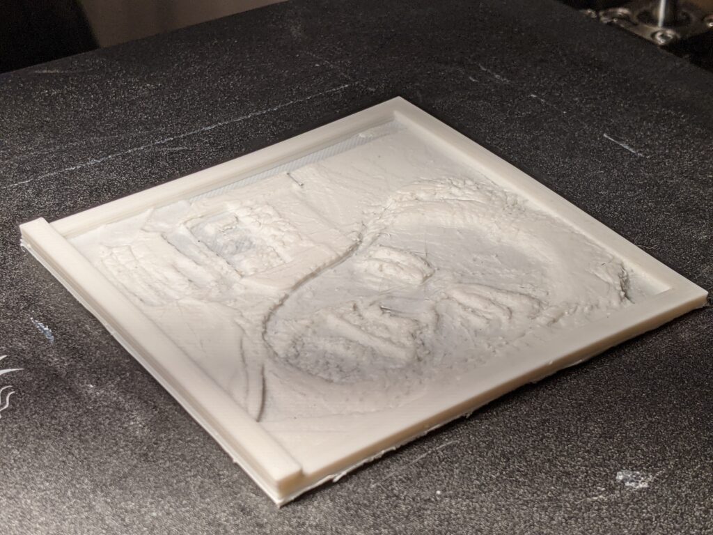
Lithophane as printed , still on print bed.
Same lithophane held up to a light source.

Latest utility print: Phone mount for Jeep JKU

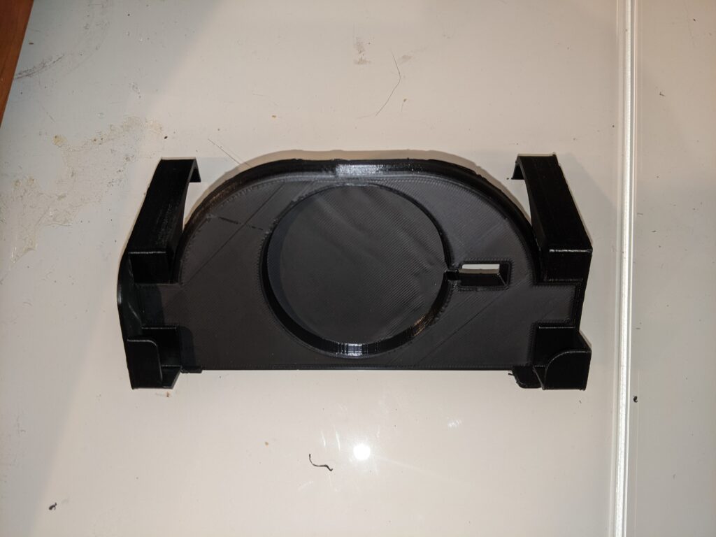
I’ve tried vent mounts, seat bolt shaft mounts, and others. Everything sucked. But some kind soul designed a phone mount specifically for the area of the dash above the radio. It clips into the dashboard tray and the gap just above the radio, without disrupting buttons if you aim it just right. And it has a cutout for a wireless charger, specifically it seems to be deisgned for the Vinsic extra-slim wireless charger. Got one on the way to try out.

One comment says that a hot day caused enough meltage for his to fall and warp. He was going to try it in another material (PETG) to see if that helped. I haven’t printed in anything besides PLA yet, but it’s about time for my experimentation to move to the next level, so I’ll keep an eye on that.

It printed in three parts — the main front panel and the two side mounts. Fitting the mounts to the front piece was a VERY tight fit, I actually had to shave the mounts a bit with a razor, and still had to tap them in. Nice solid piece overall, and fits my Pixel 3 snugly.

Source: https://www.thingiverse.com/thing:2769593

Cornstarch solves more household problems

Ever since adding the two LACK shelves to my music lab, using the computer in there has been annoying. Actually, it was annoying before. The table is too low to use it while standing, so I either had to bend a little bit or sit. And since adding the monitor, sitting is a non-starter, because I’m staring up into the abyss.

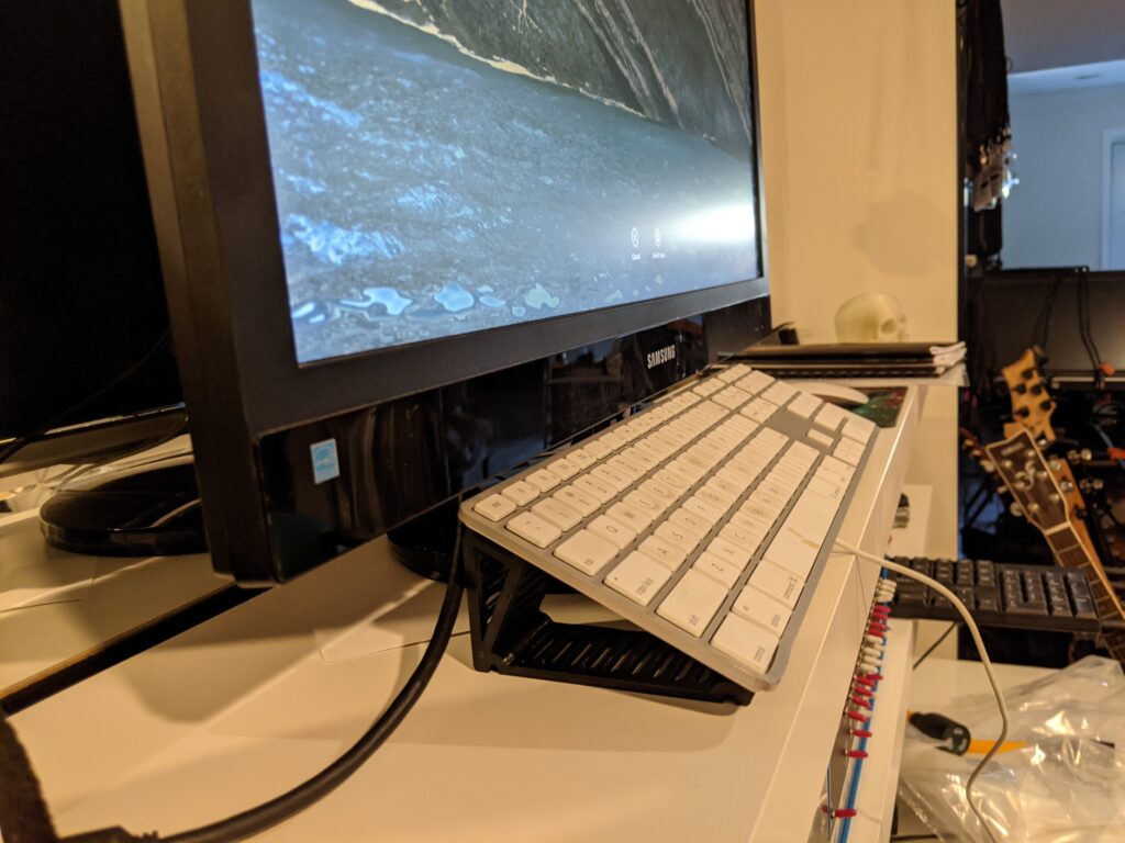
I tried placing the keyboard up on the shelf, but the shelf is fairly narrow, and the monitor base got in the way. So off to Thingiverse I go, yet again, in search of Apple keyboard risers. I found this one, which looked promising. Initially I was looking for something I could adapt to have a slight overhang at the front end, so that it would be anchored to the shelf. But this one, bless the designer’s heart, has three insets for 5mm rubber beading. Two on the bottom, to keep it from sliding on a surface, and one on the top, to help keep the keyboard itself stable, although the channel for the rear undercarriage should keep it well in place.

Now the keyboard is right in front of the monitor, perfect for the occasional standing Google search or setting it up to monitor Octoprint. Rubber beading is on the way, but it’s reasonably stable without it!

Source: Thingiverse: https://www.thingiverse.com/thing:2811956

Filling my life with specialty cornstarch…

Yesterday I decided I was tired of using random nearby objects as a riser for purposes of elevating my airpod case in the wireless charger to where it can reach the level of the charger.

I started looking on Thingiverse for random airpod cases to see if one could be adapted for this purpose. Lo and behold, I found one. This one was offered as a Tesla-branded holder, but I chose the unbranded alternative that was also offered.

It sits nicely in the cradle, and elevates the case to just the right level to receive a charge.

Did you know that PLA is a thermoplastic derived from cornstarch? This was a recent revelation for me. It’s even compostable!

I find myself paying more attention to household annoyances and organizational challenges that can be solved with 3D-printed objects. My eye is frequently with the intent to design something, but every time so far, I have found something on Thingiverse that can be used without having to design from scratch. I am grateful to Thingiverse for providing this platform, and to all of the makers out there that put their designs out there for us to use and remix.

“Making” useful things

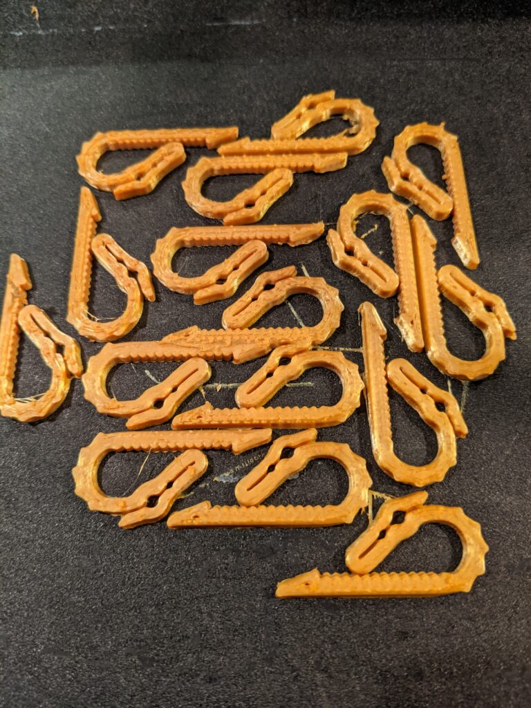
I printed a bunch of these today. Dual purpose, really. The intended purpose is to solve the “tangled filament” issue, where loose filament on the spool backs up when not under tension, and crosses under another row, and when being fed, it sometimes catches and stops feeding. If you don’t catch it, it will fuck up a print for sure.

Dragon clips

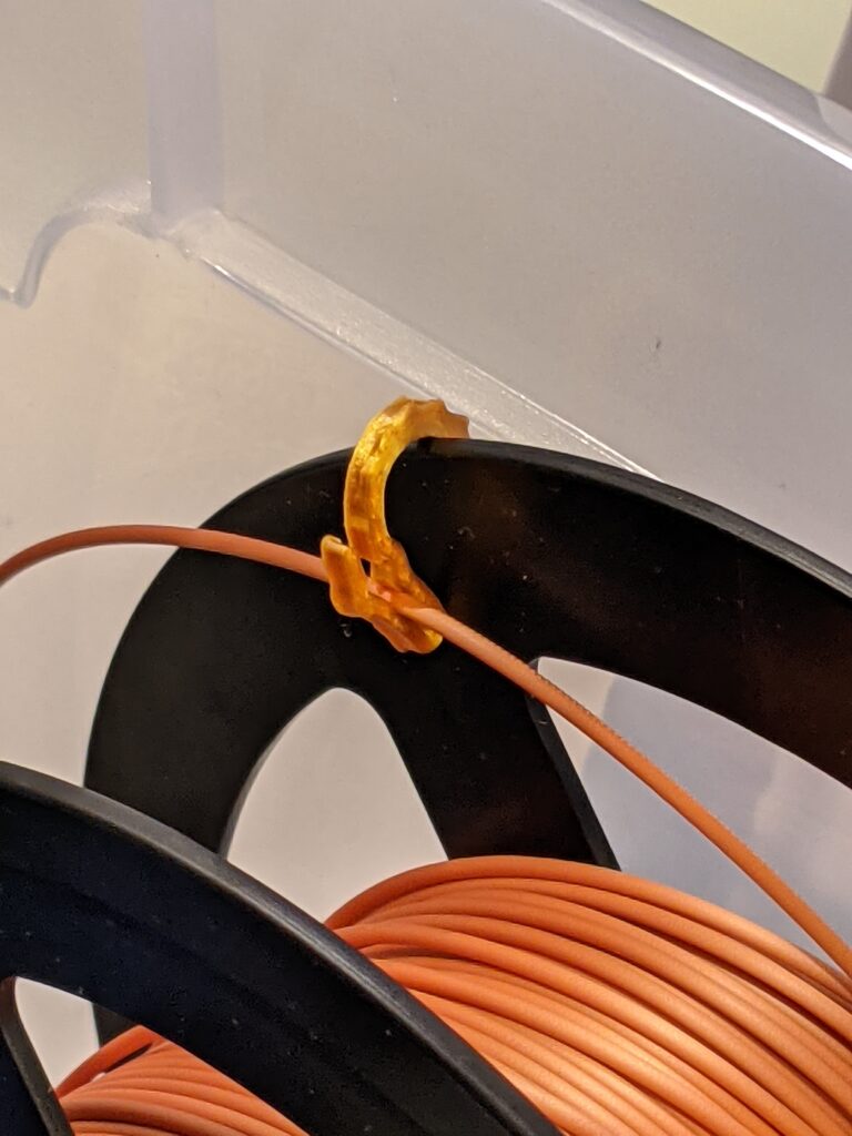
They’re called dragon clips, and they clip to the side of the spool, and have a smaller clip into which the filament clips snugly, keeping it taut when not feeding the printer.

Dragon clip in use

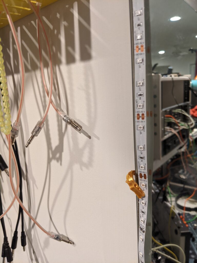
But when I printed this, I had an additional use in mind. My UV LED strips around my music lab tend to fall away from the wall mirrors they’re attached to as the adhesive backing fails over time. The strain of cables pulling on them tends to amplify the problem.

I was really hoping these clips would fit behind the mirror and hold the LED strips in place, and it looks like they’re going to work fine for that purpose.

Simple fitness timer / Arduino Uno R3

I’ve been working out religiously this year, and reading up on getting the most out of my workouts. I read something about optimizing the rest time between sets, and I started wondering how to best track that. The phone is a pain, because unlocking it, getting to an app, etc. is distracting and takes time. Laptop, same thing, plus I have to have a laptop in my workout area.
I started thinking, well, I have a whole bunch of unused Arduino Uno units and a 3D printer, maybe I could cobble something together. So what do I need? I want simplicity, so a box with buttons and a display.

I found this case shape on Thingiverse: https://www.thingiverse.com/thing:845415

It’s built for an Arduino Uno and the DFRobot LCD 1602 shield with buttons. The case even has 3D-printed button extenders that are used to press the buttons on the shield. Simple yet elegant. Ticks all the boxes.

I ordered the HiLetGo shield for $6.49 here: https://www.amazon.com/gp/product/B00OGYXN8C/ref=ppx_yo_dt_b_asin_image_o01_s00?ie=UTF8&psc=1

…and started printing the case. I decided to print in two colors for cool points. Black for the bottom case and buttons, silver silk for the top. Came out OK. I might sand & finish it later.
The shield arrived today. I quickly cobbled together some test code, attached the shield to one of my spare Unos and uploaded the sketch.

Nothing on the display. The backlit was lit, but nothing on the display.

Turned on serial in the code and added some debugging. Uploaded again. OK, good news, the Arduino is working, it’s moving around in the code, my button presses are recognized.

I tried adjusting the contrast via the onboard pot. Nothing.

Went to the amazon reviews/comments for the device. Finally found the relevant comment: “Adjust the ‘pot’ for contrast just realize this style pot takes ALOT of turn to get to the other end.”

So, with my tiny screwdriver, I turned and turned, for way longer than I would have expected, and eventually my sample text showed up.

Now I just have to write a quick sketch for button-initiated 60- and 90-second timers, and I’m good to go! Quick, no-fuss timer with customization capabilities and a simple interface and display. Might add a sound feedback in a future iteration.

UPDATE: Here’s my first stab at a script. Up gives a 60-second countdown, Down gives a 90-second countdown, and the screen shuts off when it’s done so you don’t even have to watch it closely. Screen shuts off after initial display, SELECT to see the very few instructions again.

https://github.com/dc540/arduino1602ShieldTimer

UPDATE 2: Here’s a link to a buzzer that will fit in this exact case. It’s not super loud when wired directly. Supposedly a transistor might kick it up a notch. https://www.adafruit.com/product/1740