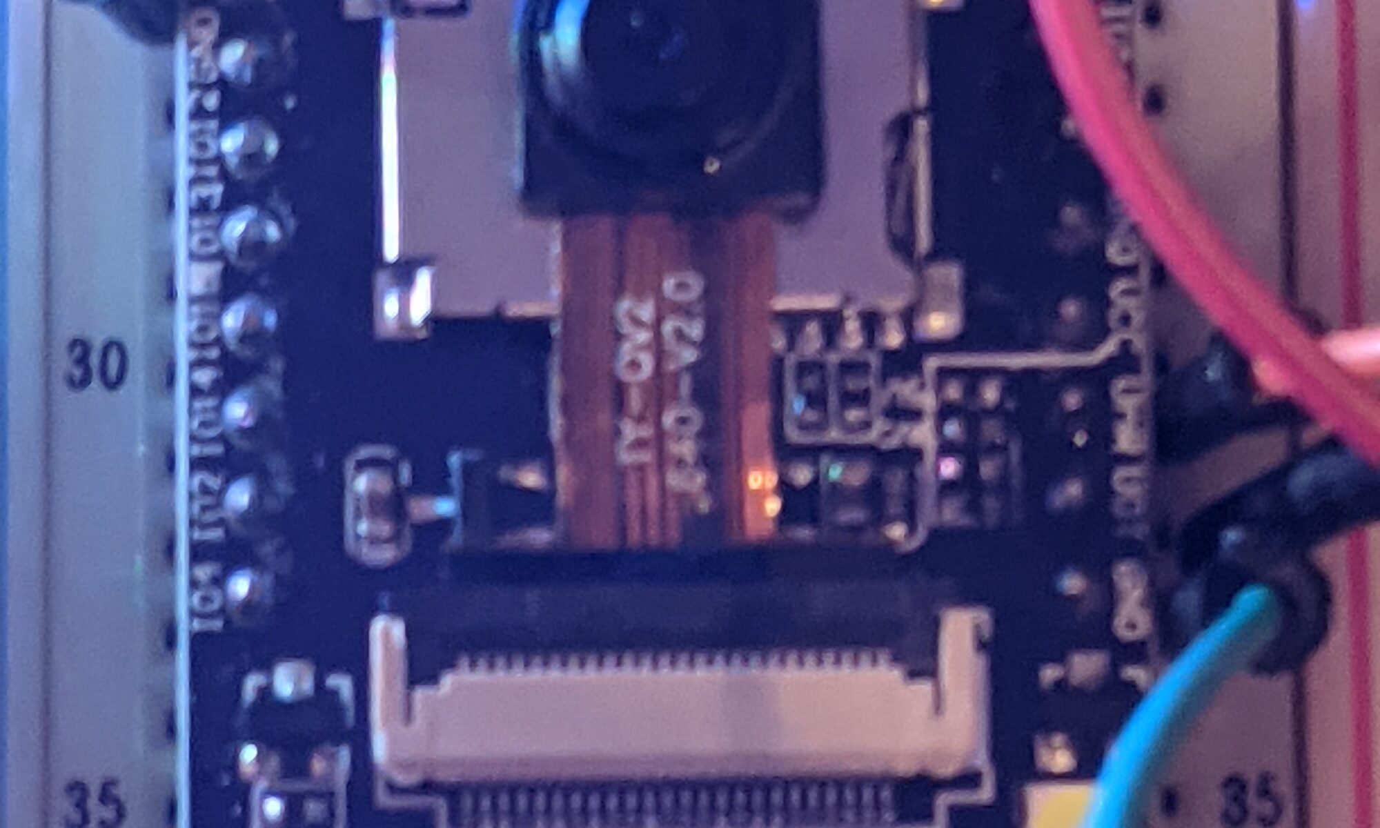
Tonight I finally got around to firing up the ESP32-CAM I’ve had sitting in a drawer for long enough to forget exactly where it came from or what it came with.
It’s an annoying little buttmunch of an ESP32, because it didn’t come with a USB programming port. This means you have to wire up a USB-TTL FTDI programmer, ground IO0, and hit the reset button to program it.
I used the Arduino-provided example. Once you install the ESP32 boards via Boards Manager, it becomes available under ESP32->Camera->CameraServer.
All you really need to do is specify the board, fill in your SSID and Wifi password, and upload the sketch. It took a few tries, but it finally came up. Once it came up, I could see on the serial monitor that it had received an IP address. I browsed to it and was surprised to see the many options available in the example software. Face recognition is in there if you drop the resolution low enough.
In such a tiny, low-cost, low-power package, I could easily see building very cheap hidden cameras out of these and integrating them into your security/surveillance package. In fact, there are dozens of housings available on Thingiverse.
Here’s an example of someone who took the ESP32-CAM to the next level:
Ever since the first time I read about 3D printers, I knew I had to have one. Something about creating things out of filament, and imagining and designing those things, has always appealed to me.
If you’ve read anything here, you know that my first was the Anet A8. Someone (probably in an Anet forum) said “Don’t buy an Anet if you want a 3D printer. Buy an Anet if you want to learn how to build a 3D printer.” Boy was that true.
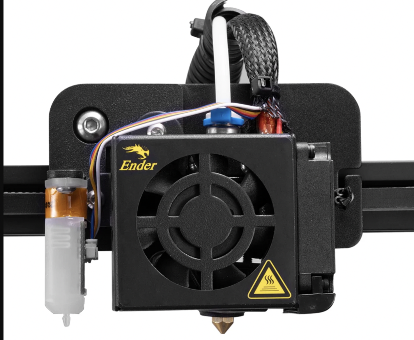
Now I have the Creality Ender 5. The price came within a comfortable reach, and the reviews have been stellar, both public and via word-of-mouth. It’s been rocking pretty steady since I got it, around the beginning of this year.
But the more you drill down into a 3D printer, the more you see how things can be improved. I soon realized that the questionable first-layer problems I have occasionally might not be a problem with my practices after all… It might just be about barely-perceptible warps in the bed, which are common. So I thought, what the hell, the BL-Touch bed leveling sensor is cheap, I’ll just get one, install it, and all my troubles will be gone.
Except that 3D printing, like most amazing things in technology, is based on rickety scaffolding and band-aids, and just about everything is more complicated than it looks. Here’s what I encountered, in semi-sensible order.
Adding BL-touch support requires making tweaks to the Marlin build.
Making tweaks to the Marlin build requires re-flashing the firmware.
Since the Ender 5 (Creality V1.1.4 motherboard) does not include a bootloader, I had to flash a bootloader prior to flashing firmware. The bootloader allows for flashing firmware via USB.
Flashing the bootloader requires using a USP-ISP or an Arduino Uno flashed with ArduinoISP to connect to the ISPC programing headers on the motherboard.
I used an Arduino Uno. I lost significant time to learning that a 10uF capacitor needs to be connected to the RESET and GND pins of the Arduino so that (as I understand it) the reset signal won’t be interpreted by the inline Arduino but passed forward to the target device. But yay, once that was done, I was able to reliably upload the bootloader. More importantly, I could take my laptop out of the equation and upload the firmware to Octoprint and use the firmware updater plugin to apply new firmware. This is much more streamlined because there’s no constant disconnect/reconnect of cables.
Meticulously following a guide for my specific printer, I was surprised when the orientation changed. Home/0,0 used to be in the back left on this printer with the stock Marlin 1.1.6 firmware on it. Imagine my surprise when my first test print started printing as if it was oriented in the diagonal opposite corner. This has cascading effects, from my calculation of nozzle to probe offset, to the move-out-of-the-way-to-pose-for-a-photo behavior for Octolapse, to the location of my Wyze Pan-Cam mount.
The whole concept of direction and home on a 3D printer, once it becomes disrupted, is extraordinarily confusing, and if you get it wrong, your shit will try to slide out of range and make a bunch of noise, and cause unnecessary wear on your parts.
The good news is, the probe “works” — as in it deploys and retracts, and senses surfaces. I still have more work to do with directions, inversions, and home locations before it correctly knows what’s going on, though.
Oh, and I also had to learn how to navigate VSCode/PlatformIO, because there are “issues” compiling this firmware via the Arduino IDE, which I had always used in the past.
I also had to disable certain less-than-necessary components of Marlin to build a firmware image that would fit in my ancient-ass 8-bit board. This probably means it’s time to replace the board with the fancy new 32-bit board, but as long as I can get this one to print, I think I can wait on that one.
All in all, I think I’ve dumped about six hours so far into this “improved experience” modification.
Improvements so far:
Incomplete BL-touch support
Disrupted orientation that still isn’t fixed
Marlin firmware went from 1.1.6 to 2.0.8.1. That’s got to be good, right?
If you followed my previous post, you’ll know that I’ve been battling with one of those $20 LED 8x8x8 matrix kits recently. It was very frustrating, there’s little support out there and confusing information, and when you’re in that state you start to doubt yourself and assume you must have done something wrong. But I tested everything I could possibly test and I was convinced I did everything right.
At that point, all signs pointed to a chip that needed programming, and I tried with numerous sets of instructions and at least four separate programming adapters. Nothing was working, and the display stayed in its broken state.
I came up with two final plans. First, I would buy a new 12C5A60S2 IC, and see if that one would program correctly using the various adapters I have. Failing that, I would fork over the $20 for an entire new kit, build the base and test it extensively before attaching the LED faces to it.
The replacement chip was $5 shipped, so I pulled the trigger and waited. The chip arrived last night, but I wasn’t motivated last night, so I hit it first thing this morning.
Keep in mind, this is a “new” chip, allegedly.
I pried out the old chip, and carefully inserted the new one into the socket. I powered the unit up, thinking I’d spin around in my chair to access the programming interface (I’m using a Pi4 with the USB programming interface because linux supports the drivers natively). Imagine my surprise when the animations start scrolling on the LEDs.
What the everloving fuck? I bought what I thought was a brand new chip, assuming I would have to program it. Only to install it and discover it already has the animation firmware I need for my project?
Best as I can guess, this project is by far the most popular reason for people having these chips, and either it’s a return that someone programmed, or they preprogram all of them as a burn-in test. I might actually have to follow up with the ebay seller, because this has broken my brain.
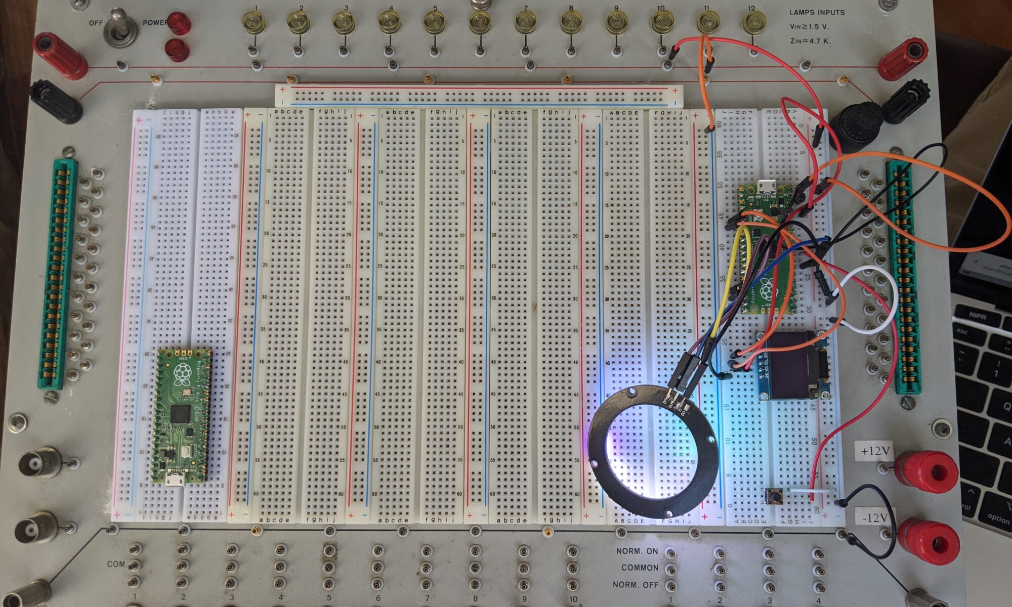
A few weeks ago, I came across this vintage powered protoboard system on FB Marketplace. It seemed to be priced reasonably for its functionality, and the owner stated that it was working. So I snagged it. I admit I was tired of working with individual breadboard strips and cheap chinese power supplies, and wanted something larger and more stable. The fact that this provides 12V and 5V and a number of lamps, switches and buttons made it much more attractive.
I started looking online for a manual for it. It’s not a complicated unit, but I wanted to know what the manufacture intended for use case and workflow. So far I have been unable to find much on it other than a brochure on archive.org and a YouTube video from “IMSAI Guy” who picked one up for free at a junk drop-off location in Santa Clara. IMSAI Guy’s video was extremely helpful, as it gave me some clues about usage and expectations. Much of the board is unlabeled, but fairly intuitive. +12V and -12V terminals on the lower right, and two bare GND terminals near the bottom of the unit, are the only terminals that are labeled.
On the video, IMSAI guy shows two pairs of red terminals near the top, one on the left side and one on the right, and it sounded like he was saying that they are 5V terminals tied together. Here’s where mine starts to differ. Rather than two pairs of red, I have two red/black pairs. I powered it up and grabbed the multimeter. Measuring from red to ground gives the expected 5V. Black to ground gives zero. Is this another ground? Hmmm not quite. Red to black gives 4.7V. At this point I’m a bit confused. It’s definitely the same model as in the video, but it’s different.
So I went through and tested the other features. All twelve of the lamps are functional and pre-grounded with a 4.7K resistor inline, all you need to do is tie them to power >1.5V and they light up. The ten switches are nicely configured, they provide patch points for normal on and normal off. Same with the four momentary button switches.
There are edge PCB connectors on each side which I can’t imagine using at this point in time, and a pair of BNC jacks on the left side. Those could be interesting.
So I built a couple of Raspberry Pi Pico example circuits and powered them up, just for the photo op, and to put the thing through its paces.
But I was still perplexed about the black terminals. Why does mine have different terminals than IMSAI Guy’s? I made a mental note to open it up later and figure this out.
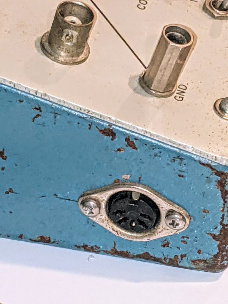
Then last night I looked at it from a different angle and noticed something I hadn’t seen before. There’s a DIN-5 connector on the left face of the unit that I hadn’t noticed before. What possible use for a DIN-5 connector would this thing have? I opened up IMSAI guy’s video again, and watched as he spun the unit. Nope, I don’t think his has this. Now I HAVE to open it up.
WOW. So mine is a modified unit. Getting the docs probably wouldn’t help at this point, unless this is a later model and how it was released by the manufacturer. (shrug).
I found another expired auction listing for one of these, and it did NOT have the DIN-5. So either it’s not stock or it’s a later model.
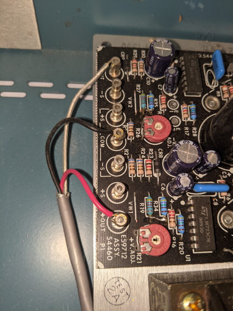
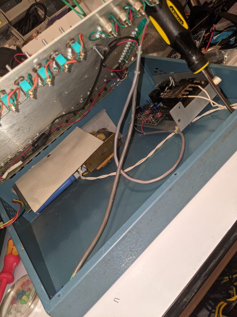
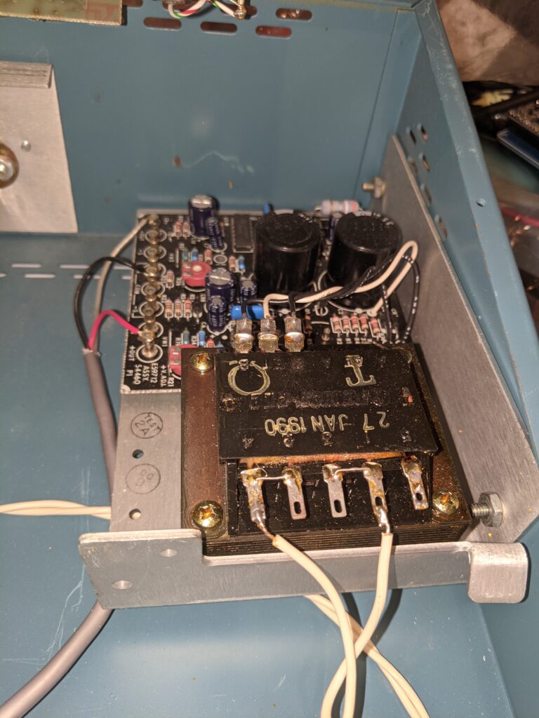
Opening up the unit, I find another board that’s not on the other two examples I’ve found. Over to the right is a more modern power supply than the brick transformer it came with. An E59712 board. And now the light bulb in my head goes on. Maybe, since this board seems to have adjustable voltage at R21, maybe it’s feeding the black terminals somehow, providing an alternative to just +/-12V or +5V. Further research required.
Add to that the fact that this subassembly is tied to the main power supply, the DIN-5 connector AND the surface board, and I’m starting to get a picture of things. I’m going to have to test more, but I feel like either this is a supplemental board designed to give more flexibility to the unit, or the main power supply died and this is a more modern replacement that was shoved in. I really am curious about the DIN-5 use case, though.
Mine had a SUNY asset tag on it, in case you’re curious. Anyhow, more digging later.
Update: Here’s a PDF of the original brochure. Not as good as a manual, but useful just the same.
So I had a remote VPS in the wild giving me issues, and while addressing the issues, I decided I should update the OS. No updates available, up to date… on CentOS 7. Well, I thought it was a good time to move up to CentOS 8. Yeah, I know the whole 7 vs 8 vs stream thing is a thing, I’m not too worried about that for the moment.
Because I didn’t want to rebuild it, I searched to see if there were upgrade instructions out there for 7->8. Found some, with the usual disclaimer. “This is unsupported,” “There is no upgrade path, you must reinstall,” blah blah blah.
So I backed up what needed to be backed up in case I had to rebuild. and went for it.
The first problem I ran into is that the version of the Centos-Release package was no longer being served. And the current release actually changed names, from CentOS-Release to CentOS-Linux-Release. “Interesting,” I thought, “I wonder if that’s going to bite me in the ass later.”
Then I ran into some issues with dependencies. gcc and annobin was the top line. A quick google revealed another user had encountered this and resolved by simply “uninstalling Perl and Python3, then reinstalling after the upgrade.”
So I tried that, and got past that little obstacle. A couple other minor dependency issues, I had to uninstall python-six and one or two obvious little interfering little noids. But it rolled through. The really scary part was the reboot, because part of the process is uninstalling ALL kernels and then reinstalling the new kernel, then making sure that grub is correct.
So I opened a serial console to it, so I could watch the boot process in case something went twisty. Double-checked that backups were thorough, and let her rip! Booted off my serial console, but opened it right back up again, and boom, everything came up. Not just the CentOS 8.3 base OS, but all my exotic internet apps. I was right back to being usable again. Why was Redis on this server again? Strange.
So that’s my story, and I’m sticking to it. Score one for the documented unsupported upgrade-in-place instruction set.
Tonight’s meetup will happen as usual, 6:30 on the Discord. I will be ducking out early to attend another meeting, but y’all are welcome to hang around after if you want.
I was about to pull the trigger on a network-enabled Fujitsu ScanSnap scanner, because I’ve been scanning on my Ricoh all-in-one that doesn’t do duplex, and I have a number of two-sided documents to scan. I was annoyed at the price tag on what seems to me to be not much more innovation than the older machines, which lack only networking.
Makes perfect sense. Set up a Pi to do the networking, then just get a SANE-enabled scanner and off to the races.
So I checked the SANE supported scanner list, and found that the ScanSnap S1500 or S1500M (pro-tip: they’re the same) was a good choice — a snappy duplex scanner with ADF, USB-connected, for a good price point, about $100. Picked one up in great condition on ebay, and it was absolutely up to the task. For testing, I used the Raspberry Pi 4 (4GB model) that had been commissioned for OctoPi for the 3D printer, and figured if it worked well I’d order another.
Well, following Chris’ blog post, I got all the scan functionality working, but even with other resources I haven’t yet figured out how to get the ADF button to trigger the scan. I’ve got the udev rules in place, everything should be running, but I still had to trigger the scan manually from the pi. Then I noticed that when I triggered the scan and nothing was in the scanner, it was a simple failure, no document detected or something like that. So I had a simple thought. I’ll just set up a cron job to run every minute and make an attempt to scan. If nothing’s in the feeder, no harm no foul, move right along. If so, scan that shit and send it to the Mayan EDMS share. Happy happy joy joy.
So now I just drop a doc into the feeder, and within a minute it’s on its way to the EDMS. Exactly what I was looking for. New RPi 4 is on the way.
UPDATE: It was migrated to an RPi 4, and I changed the single cron job to do the scans to a collection of cron jobs that run every five seconds.
Since triggering a scan does nothing if there’s nothing in the feeder, I added a simple lockfile test to the scan job: If the lockfile exists, bail. If not, create the lockfile, attempt to scan, then drop the lockfile. That way if a new scan is triggered during an existing scan run, it will abort.
Years back, I hosted several large photo galleries on a public website. Password-protected, but my family was the only consumer of the data anyway.
I decided to migrate that to my growing internal network, because I have disk space, backups, and faster networking. Plus that old gallery software was getting long in the tooth and I didn’t feel like continuing to maintain it.
Dilemma: The old gallery was one of those, like most of them, that import the files, give them a long filename and remove the uploaded copy. So there was no rhyme or reason to the 11G of photos on that server, just a single flat gigantic directory of JPG files, over 1500 of them in total.
It only took a few minutes to realize that there seemed to be three paths — (1) a fully manual path of uploading all of the files in a batch into the new photo management app (I’m using Lychee, by the way) and then sorting through them; (2) a less manual, but still involved, path of logging into the old gallery and exporting/downloading each set; or (3) finding a smarter way.
I chose (3) finding a smarter way. I realized that my photo sets were all event-based, and the date of those events are stored in the EXIF data of each individual photo file. So I wondered if there was an easy way to extract that in a useful way, and then possibly script it to segregated it by date. I quickly found something even better — the exiftool itself (installed on my macbook with Homebrew) will easily do exactly that:
Will siphon through an entire directory, lickety-split, pull out the capture date from the EXIF data, and then file them in a directory named for the YYYY-MM-DD of the date. It will even create the directories if they don’t exist. I went in seconds from a flat directory of over 1500 files to, let’s see…. 12 individual date directories, each filled with a day of photos.
Lychee lets me import directories and will name them “[IMPORT] (directory name)” so all I have to do once they’re all imported is to log into Lychee, look into each newly-imported directory to figure out what the event was, and rename the album. Fun stuff.
Just a little curious exploration. I googled something, happened to notice that there was a takedown listed for that search result, so I clicked on it to see what it was. Did you know you can get the list of URLs on the takedown request by just supplying an email address?
None of this is what I was looking for, by the way. [file attached]
DC540 has been accepted into the O’Reilly Community Partner program. There are resources available through this program, we will share more info on that as it becomes available.