K40 Laser Calibration: Center That Beam!

We’ve been fighting with the K40 for what feels like months. Finally got it “working” reliably a few weeks ago, but at a higher power level than I expected, and it was still not cutting all the way through acrylic. Good enough for production — we could break off the pieces — but I knew from anecdotal evidence that it could be better, so I was disappointed.

Fortunately, it clearly went out of alignment this weekend. I was seeing double lines on the cuts. So I knew it needed aligning. Mirror alignment was something I had been mostly avoiding since unboxing this thing, since like a lot of K40 units, they put some sort of glue or caulk or other kind of sealer on the knobs/screws of the mirror alignments to kind of lock in factory alignment. Unfortunately, this was no longer cutting it (no pun intended) for me.

So I followed the alignment checklist, checking for alignment with the laser head at top left, top right, bottom left and bottom right, to see how far down the alignment rabbit hole I’d have to travel.

Background: K40 lasers use a series of three mirrors and a lens to focus the beam on the material in the bed. Mirror #1, right where the tube emits, takes the beam from the tube and brings it out into the play area. Mirror #2 is on the near end of the traveling arm, and mirrors the beam from #1 to mirror #3. Mirror #3 is inside the laser head itself, and is basically a stationary mirror which reflects the beam from #2 down to the material.

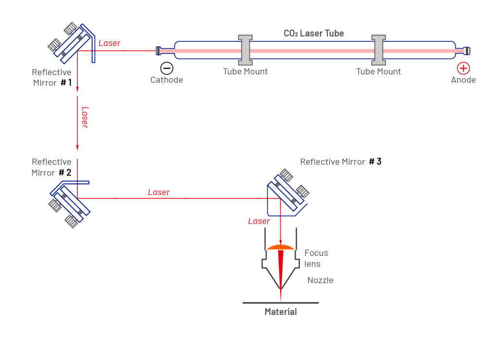
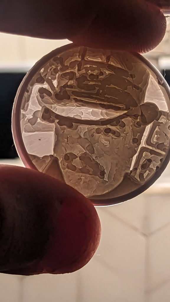
By putting tape over the hole in the laser head and then giving a short low-power burst, you can see exactly where in the hole the beam from Mirror #2 is entering the laser head. Ideally, you’re bringing that beam into the center of the hole in the laser head, so that it will hit mirror #3 dead center and thus hit the focusing lens dead center, for optimal energy transfer to the material.

Mine had been hitting fairly close to the edge of the hole, but since it was engraving and cutting somewhat satisfactorily and reliably, I had been ignoring it. The double lines showed me that it had gone further out of alignment. Sure enough, a piece of tape and a short burst indicated that the beam was striking even closer to the edge than before. So likely whatever beam was making it to the lens was weakened and skewed by the angle at which it was hitting.

So I removed the sealer from the knobs on mirror #2 and started twiddling the knobs, using additional short bursts to check my progress, until I had the beam good and centered. I checked it at the four positions to ensure it was at the same position in all four. If not, I might have had to start working with mirror #1, which I was hoping to avoid due to added complexity. I was lucky. It was dead center.

I ran another test, and it came out perfect. No double lines, and none of the items on the 8×10 panel I was cutting required breaking off. This indicated to me that more energy was reaching the material surface, and thus I could potentially reduce power and passes and still have good results.

With the next two panels, I reduced by 5% power each and one cutting pass. So effectively I migrated from 65% power and 4 cutting passes to 55% power and 2 cutting passes, and my objects are still cutting and engraving perfectly. This afternoon I might try even more reduction. It’s hard for me to imagine a single-pass cut, but I’ll try it and see.

Center that beam, folks!

Post-Meeting Breakdown

So we had two new folks show up at tonight’s meeting at the Arlington Library. I’d consider that a success. Thanks to Spud for putting the feelers out there on Reddit. Quincy Hall, a pizza & beer hall around the corner from the library, was great. Decent pizza, lots of beers, super fast service and great prices.

Tonight’s souvenir coin was a lithophane of my amazing face. A lithophane is sort of a topographic 3d print of a photo so that different levels of shading are represented by corresponding thickness in material. The end result is something you can hold up to backlighting and see the image as if it has been printed.

Public Meetup Alert

Here we go again. Our second Public Library meetup of 2023! Monday 11/27 at the Arlington Central Library, Quincy Room. 6:30pm. Public-transit accessible.

The room seats 16. We have no idea what happens if we reach capacity. Let’s test the system.

There should be trinkets available for those who sign the guestbook. Probably stickers too. Maybe a door prize or two. Who knows what’ll happen with this bunch?

DC540 Library Meetup!

We haven’t met in a public library since 2019! And here we are.

Gum Spring Library, Meeting Room B, 6:30PM on Monday. Since it’s the evening before Halloween, well, if you feel like a bit of holiday participation, please feel free. This meeting is open to the public, or at least as much public as we have room for. Let’s get to know each other without a strict agenda. But we do expect there will be some badge design discussion.

Recording Modular Synths

A while back I made an executive decision regarding my modular collection. I decided that I wanted the setup to be as portable as possible. The problem with that is that the year prior, I had bought a TASCAM DP-24SD. Yep, I had all my modules’ audio outs going to a full-sized mixer. I even had a 16-channel submixer in a 1U rack. I’m not sure what I was thinking, but I had managed to fill every input.

So I picked up the WMD Performance Mixer, just after they decided to cease manufacturing. I loved how I could do effect send and return, lots of out options, cue, and it had plenty of channels. Not as many as the Tascam, of course, but I really don’t need that many.

I sold the DP-24SD, and that left me in a quandary as to how to record my glorious synth grooves that nobody understands but me. I picked up a DP-006 for a really good deal and that seemed fine, except that it’s very cumbersome to use. You have to record to it, then before exporting a song via USB, you have to master it, which takes as long as playing it. Here’s my shitty opinion. If you’re recording on a dated, sub-$100 digital recorder, you probably don’t need on-board mastering.

I used it, frustrated a few times, then realized, holy fuck, I still have a DR-07 that I used to use to record live concerts. Dug it out, recorded a session, straight to MP3, and it transferred over with ease and sounded great. Nice to breath life into that old thing. Other advantages: While the DP-006 inputs are 1/4″ and required adapters to come out of the WMD Performance Mixer, the DR-07’s line in is 1/8″ stereo and I can go direct with no adapters!

And on the opposite end of the spectrum…

So we talked about weird-ass 1.8″ drives, and now let’s look at the other end of the spectrum. Dell has been putting these out on servers lately. I especially like them on the T350 tower server line. There’s a barely-perceptible opening on the faceplate where the carrier bracket slides out.

It’s the BOSS-S2 module. A weirdly engineered, SATA connected M.2 controller. What’s weird about it, you ask? Well, the module has two slots for a pair of M.2 carrier cards mounted in opposite orientations. The module has a built-in RAID controller, which makes it perfect for an OS boot “drive.” A pair of M.2 drives in a RAID 1 configuration makes a great choice, and frees up all your front-panel drives for storage.

Weird obsolete server configurations…

One of our members picked up a server for a homelab recently. It was a good deal, an R730XD populated with a decent amount of RAM, two SSDs for OS boot, and eight spinny drives for storage. I helped set it up.

It was ready to party right out of the box, and we installed ESXi on it right away. But the server was outfitted with something I’ve never seen before.

So let’s count the drive bays on this monstrosity. 2x 2.5″ bays in the back (for the boot SSDs) — this is actually a great arrangement in my opinion, to keep them separate from the storage drives. On the front, two rows of four (or is it four columns of two?) totalling 8x 3.5″ drive bays. I like 3.5″ drives for storage, because you can fill it up with the 12Gbps high-capacity SAS drives, and they’re super-affordable.

What’s weird about that? Wait for it…

Above the 8x 3.5″ drive bays are 18x (!?!?!?!?!?) 1.8″ drive bays (?!?!?!?!?!?!). First of all, I’ve been doing this for a minute. What the fuck are 1.8″ drives? They must have gone obsolete as soon as they were released, because I’d never seen them before.

Social House meeting this evening

We’ll be meeting at Social House this evening. Trying out a new thing where we offer small custom souvenir collectibles to folks that show up at meetings. Gotta catch ’em all. We’ll see if this takes. It fits well with our upcoming “library tour” plans.

Social House in South Riding, VA. Approximately 1830. Look for the table of nerds.

Lanner 1U network appliance LCD panels

I’ve found these Lanner 1U network appliances incredibly useful. Nice small factor, lots of network ports to do fun things with. They make fantastic Linux routing appliances. They’re kind of old-school, though, they have these LCD panel modules with four buttons.

I’ve been using them off-label for so long I can’t even remember what the panels were originally for.

See, the first thing I do is connect serial, boot to USB and install something modern on it. Rocky, Ubuntu, whatever.

Last week I went to explore the LCD panels, and see if I could make use of them. Maybe as a periodic status display or something. For the first time in years, I consulted the actual manual for these devices. It turns out, they’re connected to the motherboard internally via an internal parallel port.

The manual suggests using the drivers found at https://github.com/majodu/plcm_drv_v013 but they are so old they’re meant for Linux kernel 3 and below. So the first thing I did was clone the repository. After looking at it for a few minutes I realized I didn’t need everything it was delivering, I just needed the kernel module itself, which is compiled via the “boot” argument. Looking at the Makefile it was pretty clear what the logic was in “boot:”

boot:
ifeq ($(KVER3),3)
	$(MAKE) -C $(KDIR) M=$(PWD) modules
endif
ifeq ($(KVER),2.6)
	$(MAKE) -C $(KDIR) M=$(PWD) modules
endif
ifeq ($(KVER),2.4)
	$(CC) $(MODCFLAGS) -c plcm_drv.c
endif

So the first thing I did, since my installed platform used kernel 5, was change the KVERS3 line to ifeq ($(KVER3),5) so that it would run the make on my kernel.

I was able to compile the kernel module. It barked at something else it was trying to install, but since all I really needed was the test executable and the kernel module for now, I ignored that.

Then I ran into an issue loading the newly-created kernel module. It didn’t like the major number associated with the driver, 248. Looking at /proc/devices I could see that 248 was in use by ptp, so I edited the Makefile and plcm_drv.c to use 239 instead, since that was available. I recompiled, and was able to load that kernel module just fine. After that, the plcm_test executable successfully ran and displayed stuff on the LCD panel and accepted button presses.

Good enough for now, at least I know I can write something in C to display something and receive button presses. Now to think through a good use case for this silly hoop I just jumped through…