We created a dilemma for ourselves last year. If you saw our badge from last year, the Tree of Life badge, you’ll notice that we took a simplistic approach when mounting our OLED display. We used the version of the display with a backing PCB, and just mounted the PCB to the top board. It’s not innovative, it’s not beautiful, but it’s fully functional.
In #badgelife tradition, we wanted to do a little bit better this year. My goal was for the display to be flush with the top board, for a clean, flat appearance. At the very least, this would likely mean mounting the display on the bottom board. This creates a dilemma:
- If mounted via header pins and therefore removable/replaceable, the backing PCB of the display ends up at the same height of the top board. This is undesirable, because the backing PCB is larger than the display and inelegant. The goal is to have just the display itself rise into a cutout in the top board.
- I could certainly have soldered the display directly to the bottom board, but since I made the design decision of mounting the display overtop and perpendicular to the Raspberry Pi Pico, , this would prevent access to the Pico in case a solder joint needed to be corrected. It would also prevent easy replacement of a broken or faulty screen.
So we looked at the problem and found several options available to us. I think the ideal solution would have been low profile female headers on the bottom board for the screens. In practice, however, we found these to be akin to Unobtainium. The only place sizes were properly defined was on Mouser and DigiKey, and no, I’m not paying a dollar each for freaking headers. I did find a writeup by someone who had done the research and found some reasonable low profile headers in China, but we were on a time crunch, so those remain on the to-be-explored list.
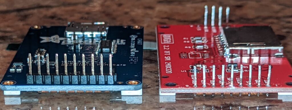
The solution that found us was to remove the “pin carrier” from the display after the pins had been soldered. The pin carrier is the extra bit of plastic that holds the row of pins together. This allows the pin to sink a bit lower into the receptacle header. Then we noticed it was bottoming out and not ending up completely flush at the top, so we ended up trimming about 1-1.5mm from the end of the pins on the display.
This solution allows the display’s backing PCB to sit just below the front board, and the display itself to sit flush, while still able to be removed for troubleshooting or inspection.
Here’s a before and after of the display modification, hopefully it helps to visualize. Note that the “before” model is actually a different model because I’m all out of unmodified stock.


