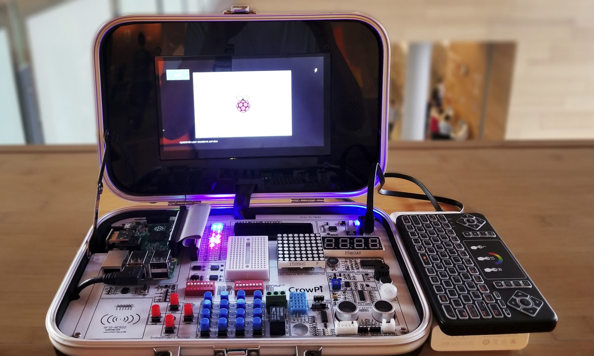
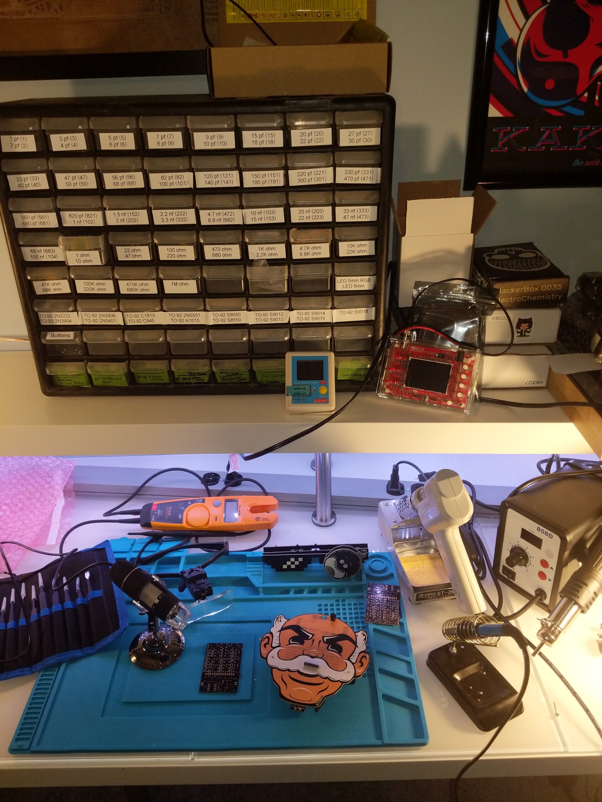
Tonight was another fun evening for DC540. Three of us pregamed at Red Dragon Brewery, then headed over to the library, where our three became five. We played show and tell with the CrowPi and the TS80 solder iron, and shared our experiences with the Pontifex crypto scheme, designed by Bruce Schneier for Neal Stephenson’s excellent book Cryptonomicon.
We decided that even though there’s no meeting on the 4th Monday of December because the library is unavailable for Xmas eve, that we’re going to go ahead with a social meeting at the brewery on Tuesday, December 18.
Interesting upcoming events: Shmoocon tickets – next round Friday. BSides Philly February 1. If anyone has extra Shmoocon barcodes and is looking for worthy buyers, look no further.
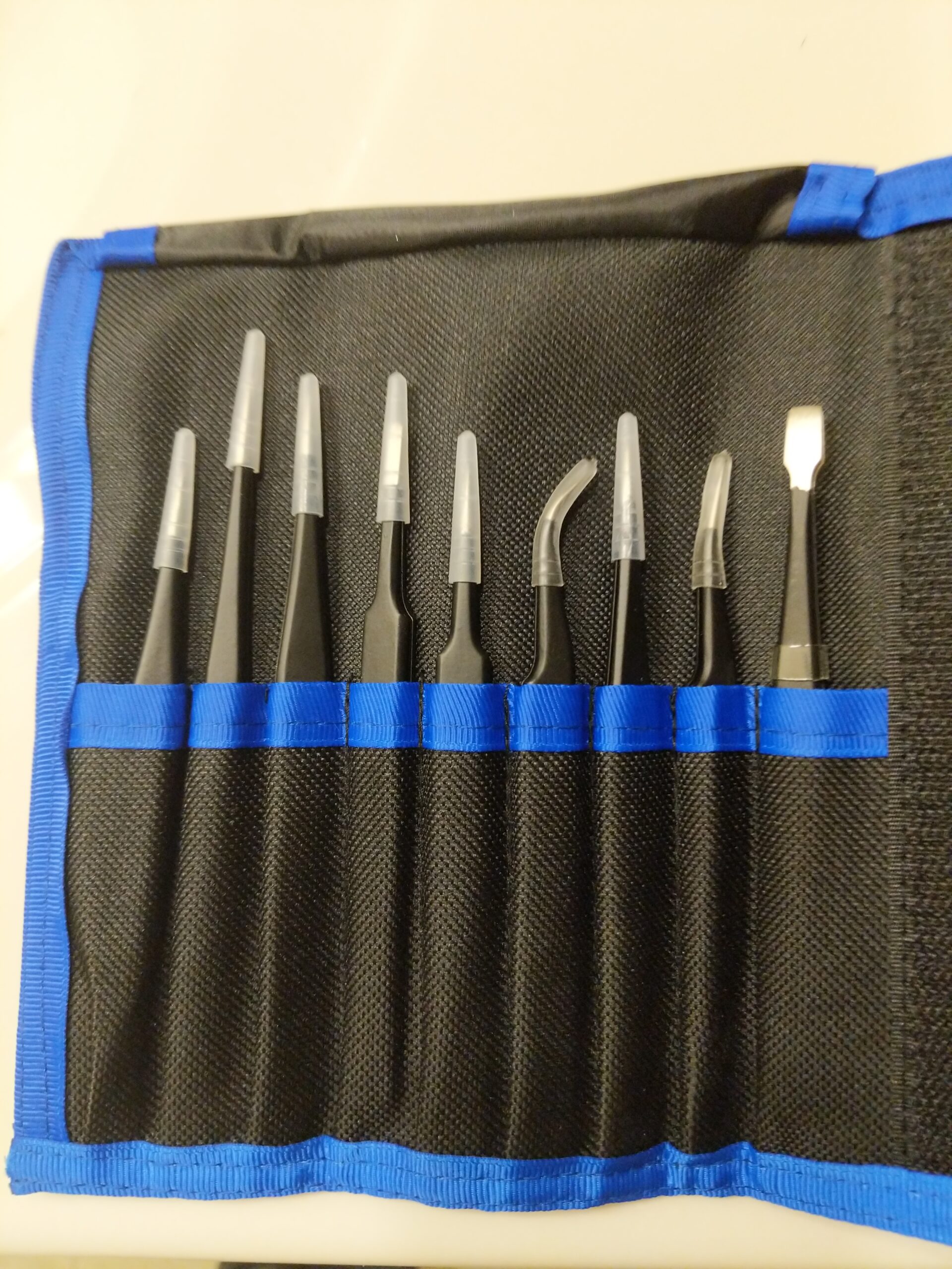
When I first started taking solder seriously, I used household tweezers when I needed. That took about ten minutes before I realized they sucked. So I bought a manicure set, hoping those tweezers would be better. After one session, the two arms broke apart.
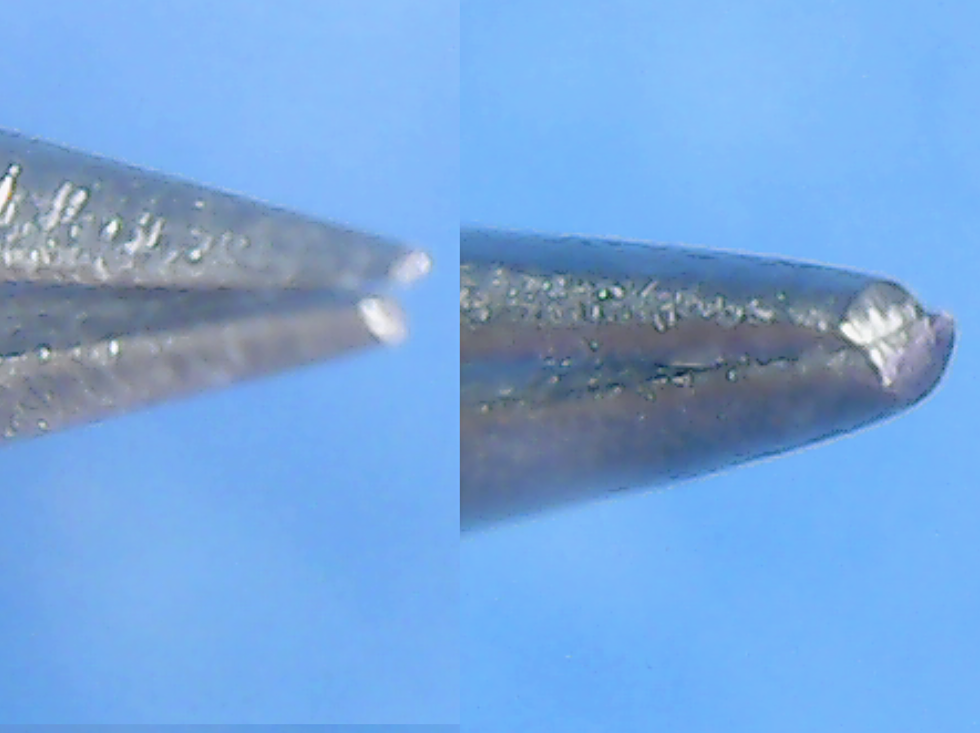
So I bought a generic set of “technical tweezers” from Amazon. Then I was told by a good friend that you really need to look at “precision tip” tweezers, and he sent me a link to McMaster-Carr’s stainless steel tweezers page. I ordered a set of Aven Technik tweezers ($33) for comparison.
On the left is the bite of the generic Amazon tweezers, which are clearly simply far lower quality tweezers designed and marketed to look like precision-tip tweezers. Look how misaligned the bite is, and how little surface area is actually making contact at the bite, compared to the Aven Technik on the right. When dealing with near-microscopic parts, the Aven will grip the part solidly, while the tweezer on the left is likely to twist it around and send it flying across the room like a clipped fingernail.
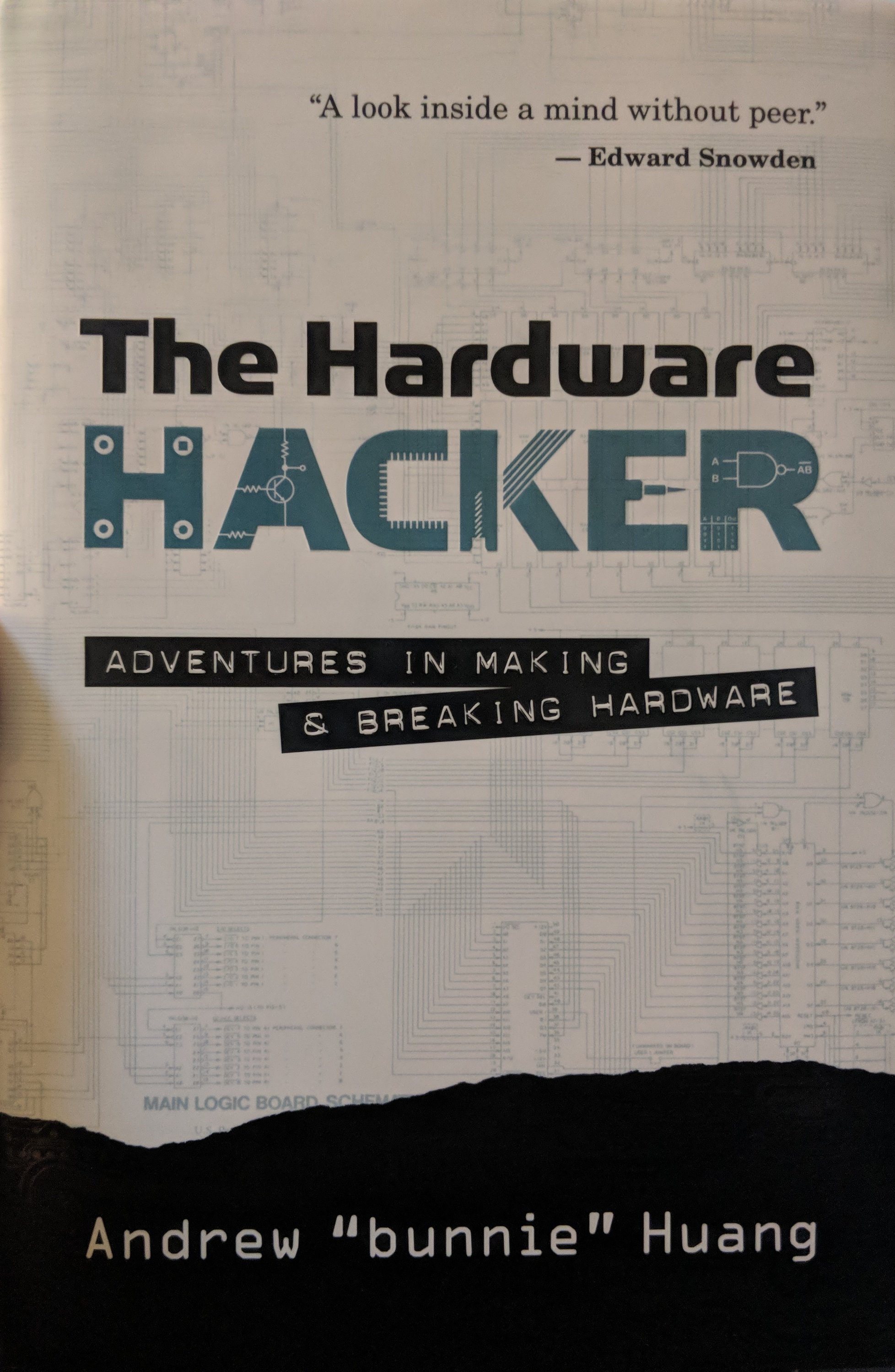
This book arrived at my doorstep yesterday. Color me excited. $12 something at Walmart, go figure. He goes way into Chinese factories, manufacturing and the supply chain before getting into the hacking part of it. Exciting if you’ve got some hardware ideas in your head.
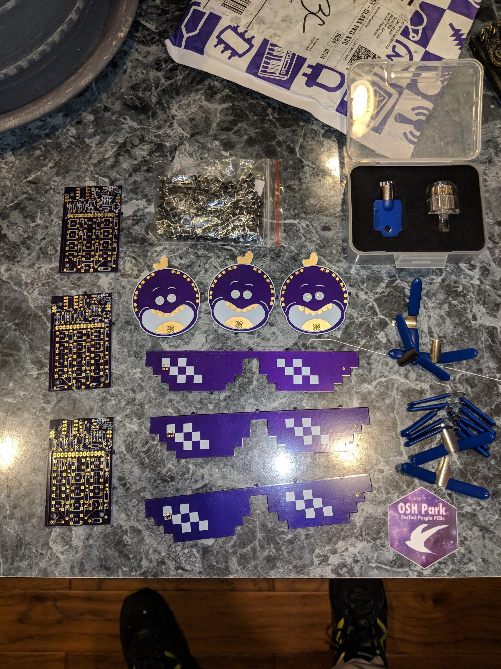
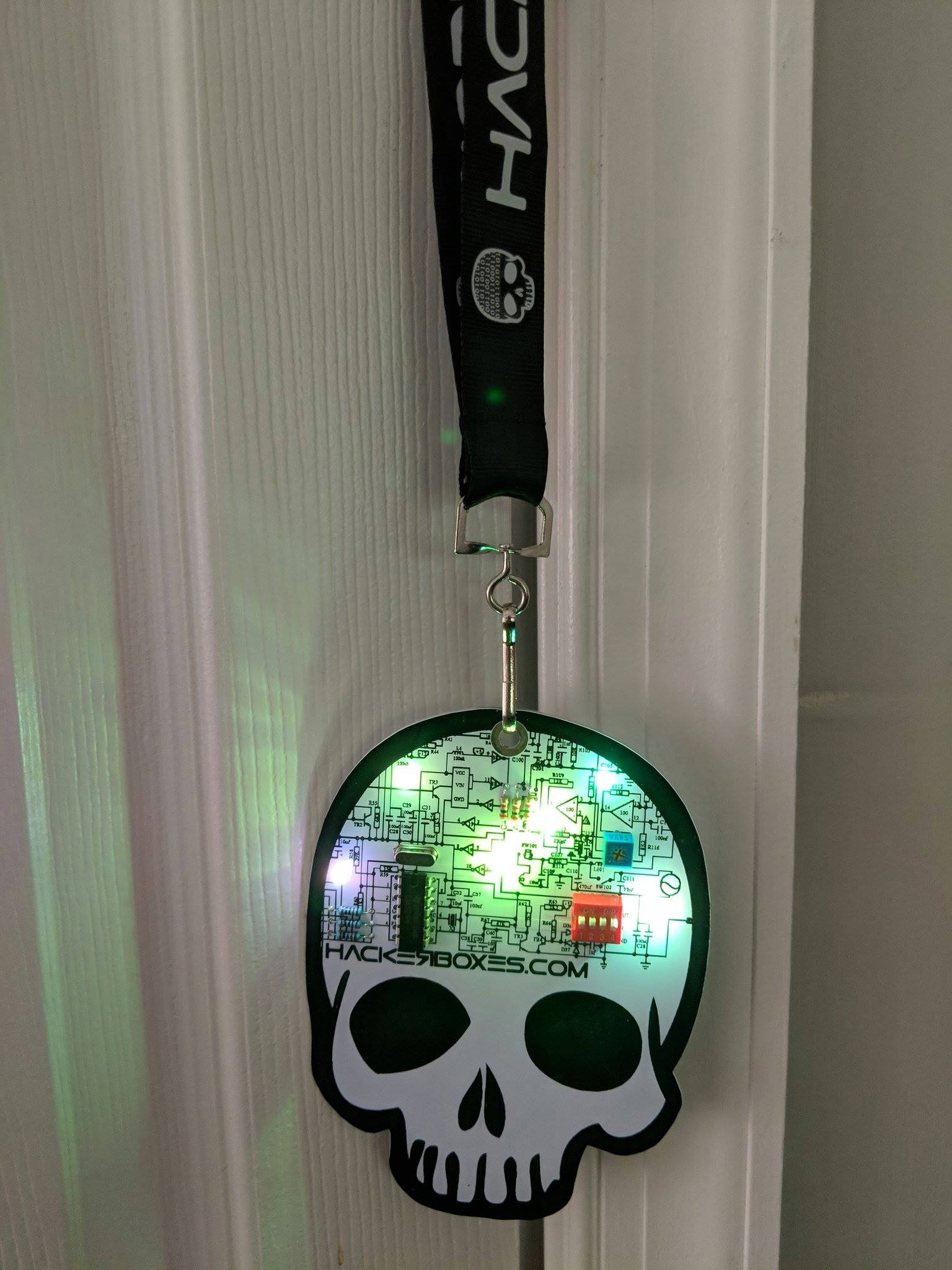
Better late than never. I think this one was released in time for subscribers to assemble it before Defcon. I slapped this together over the weekend. About the simplest project you can imagine. The switches turn the individual LEDs on, and the LEDs each have either a slow transition or fast transition IC built-in. The resistors are purely for decoration. It’s pretty and blinky, so I can’t complain.
The kit also came with a MicroPython PyBoard to experiment with. Going to have to steal some time to play with it, it really sounds like a lot of fun.
The soldering for this one was a piece of cake. Everything was nicely padded and spaced. Big pads make soldering way easier than a tiny ring.
EXCEPT for the potentiometers. The strain-relief legs didn’t fit into the PCB holes, and Hackerboxes just suggested shaping them into a tube to make them fit, without any real guidelines on how to do that. Anyway…
I hadn’t yet installed the Arduino IDE on my primary Macbook. No issues there. Had to install the ESP32 board into the Board Manager. Then I had to install the VCP USB UART driver so that the serial port would show up in the Arduino IDE.
Then, BAM. My sketch uploaded and works.
Yes, I know I didn’t install the pots yet. I also didn’t install the DAC yet. Maybe tomorrow. I just wanted to light up the MAX7219 8x8s.
I built this proof-of-concept last year. There are lots of people doing circuit-bending experiments, and the older model of the Alesis SR16 is a somewhat popular platform. It’s affordable, if you can find the older through-hole model (the surface mount version runs about the same price, and there are more of these out there on eBay et al, and it might be difficult to tell the difference. But most circuit-benders are happiest with traditional analog switches, knobs and patch cables. I wanted something a bit more flexible, and for lack of a better word, fluid.
So I set about connecting all the available/usable pins of the sound module IC to opto-isolator relays, and connecting all of the relays to a common “ground.” Then I set up a Raspberry Pi to control the relays via the GPIO pins. Then I added the 7″ RPi touch screen and slapped together a quick Python GUI for controlling the relays through the Pi, stealing some on/off switch graphics from somewhere on the net to populate the GUI.
This isn’t what I consider an end result, it’s a jumping off point. From here I can easily figure out which pin combinations generate my preferred sound modifications. I can then add buttons that apply those pin groupings as “mood” combination settings. I can add a MIDI controller so that I can automate it from my keyboard or DAW. The possibilities are limitless. Flexible, fast pin coupling changes, automation, etc.
Now that my soldering skills have leveled up a few points, I’m going to spend some time revisiting this project, and maybe mount it in a more permanent housing. What other fun things can I do from here? Oh yes, blinky LEDs? That’s a must.