I’ve been wanting to slap this together for a while. Since we have so many members who have never seen the space (thanks Covid!), I thought I’d give you a taste.
Mucking around with the 2019 SAINTCON Enigma Badge
So thanks to Kyle, I’ve got a 2019 SAINTCON Enigma Badge to play with for a while.
I’ve been mildly frustrated by the fact that I haven’t gotten anything to decrypt on it yet using the 2019 instructions, sample messages and code sheet. I had just gotten comfortable with that fact when the Hackers Challenge CTF came up during this year’s SAINTCON. I lost quite a bit of time to trying to solve an ENIGMA challenge, because I HAVE the badge right here in front of me but still had a knowledge block that was preventing decryption. Had I learned before the CTF, I would have gotten another 300 to 400 points.
So now, even though the challenge is over, I was even more determined to see this through.
Here are the 2019 instructions, with my commentary following:
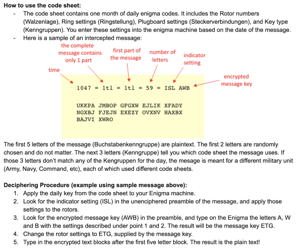
Okay. Instruction 1 says “Apply the daily key from the code sheet to your Enigma machine.” This is a sample of what the Code Sheet looks like. While it is unclear from the instructions AND the Code Sheet, I assumed that “daily key” refers to the “ring settings” or Ringstelling.

What threw me was the plugboard. When I entered settings, there was a PLUGBOARD section on the badge that wouldn’t accept any input. Naively, I assumed that was an unimplemented feature. Boy was I wrong. I wasn’t at SAINTCON last year, so I missed a critical piece — the critical piece is that the plugboard is a PHYSICAL plugboard on the badge, just as it is on the real thing.
Once that Eureka moment came (thanks to atru5 and kfeuz for clueing me in), it was smooth sailing all the way to the finish line. God I want one of these of my own.
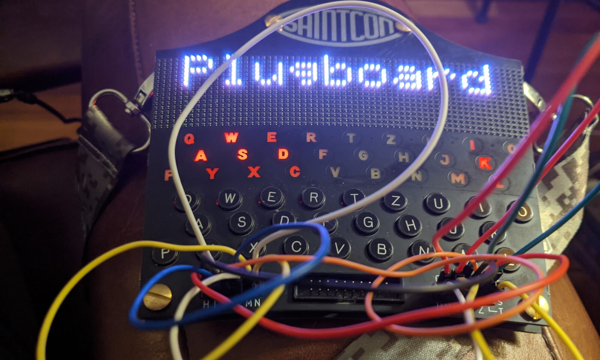
Here’s the sample message and the code sheet for that day, followed by the images of the message decoding after setting all the rotors, ringsettings and encrypted message key, and connecting the plugboard up properly with jumper wires:
October 27 1942
0801 = 1tle = 1tl = 107 = SYN VAB

SCZOT GULGK VHBJQ WILJA CBSZG YUUYC VYLFV YPEFZ SMLNR DFPEO HYHNB JFSYV JFJJP QGKRV MUJLS TLESD IISMW POMJT JBYNL LLOIC YFNWK VU


If you want to play with the Enigma yourself, you can use the simulator on Cyberchef. For the SAINTCON simulations, you will need a custom rotor. When the code calls for rotor IX, use the following: BASHCOMPUKIDZERGYJWLQTFXVN
YAPA: Yet Another Proxmark Accessory
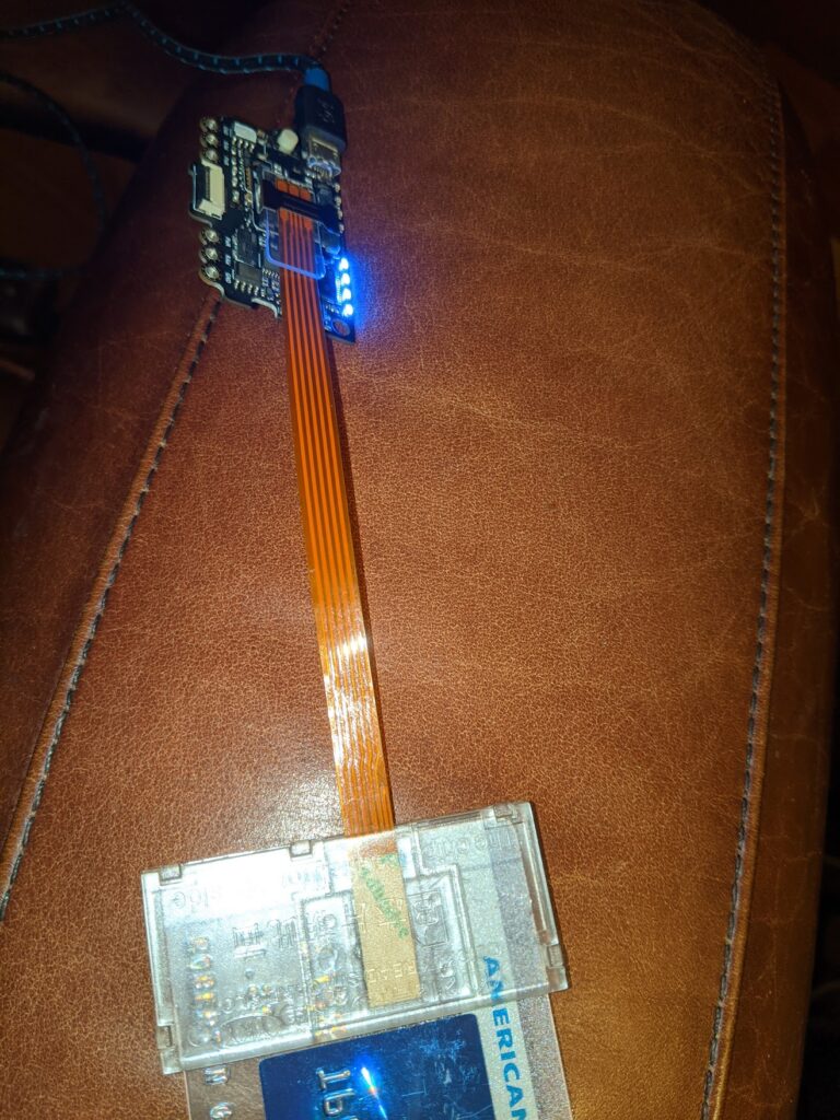
Today, one of the important accessories I was waiting for arrived. The SIM card reader extension. This extends a SIM card slot out via ribbon cable to a clear housing which fits, wait for it… a smart card. Inside the Proxmark3 RDV4 housing, in addition to all that delicious RFID goodness, is a SIM card slot. (If you didn’t already know this, SIM cards are basically the same technology in a different card profile.
So if you crack open the housing (and remove the BlueShark battery/BT module if you have one), you’ll see the SIM card slot. These adapters are less than $2 on aliexpress. Once you slide it in and slip a card into the housing (chip end first, of course, and chip facing the contacts), you have access to the sc commands in the Proxmark firmware (I’m running iceman’s fork, I don’t know how much of this is supported in the stock firmware).

Custom Flight Tags FTW
I remember when I got my Hak5 kit, one of the things I thought was a nice touch was the custom flight tags — “REMOVE BEFORE FLIGHT” on one side and “TRUST YOUR TECHNOLUST” on the other.
Anyone who knows me knows I have a fetish for storage solutions, both permanent and portable/mobile. I really like the idea of everything in its place. When done right, finding things in the heat of the moment becomes a breeze. I wasn’t always like this.
So when I started enhancing my Proxmark3 RDV4 with accessories, most of which aren’t used at the same time, I realized I would have to assemble a kit and contain it somehow, because when going out and about for RFID research purposes, I might need any of the accessories. I happened to have a zipper bag similar to the Hak5 kit, so the thought came to me, “Hey, I wonder if custom flight tags are affordable in low quantities.” Turns out they are!
I found this on Amazon — two tags, two sides of messaging, choose your colors, under $10.
https://www.amazon.com/gp/product/B085772MFD/ref=ppx_yo_dt_b_asin_title_o02_s00?ie=UTF8&psc=1
I figured at $10 it was worth a shot. For a moment I struggled with what the second tag would be for, then I realized I could use it with my locksport Pelican.
I think they came out fabulous. 10/10 will purchase again.


My SAINTCON badge came today.
What an exciting time to be alive. The badge itself will be a really fun platform for collecting minibadges. A minibadge came with it, as well as a coupon for three copies of my own minibadge, which I designed today as part of the Hackers Challenge CTF that’s going on during the con. Strongly recommend y’all get one before they run out. Very affordable for the level of fun and creativity involved.
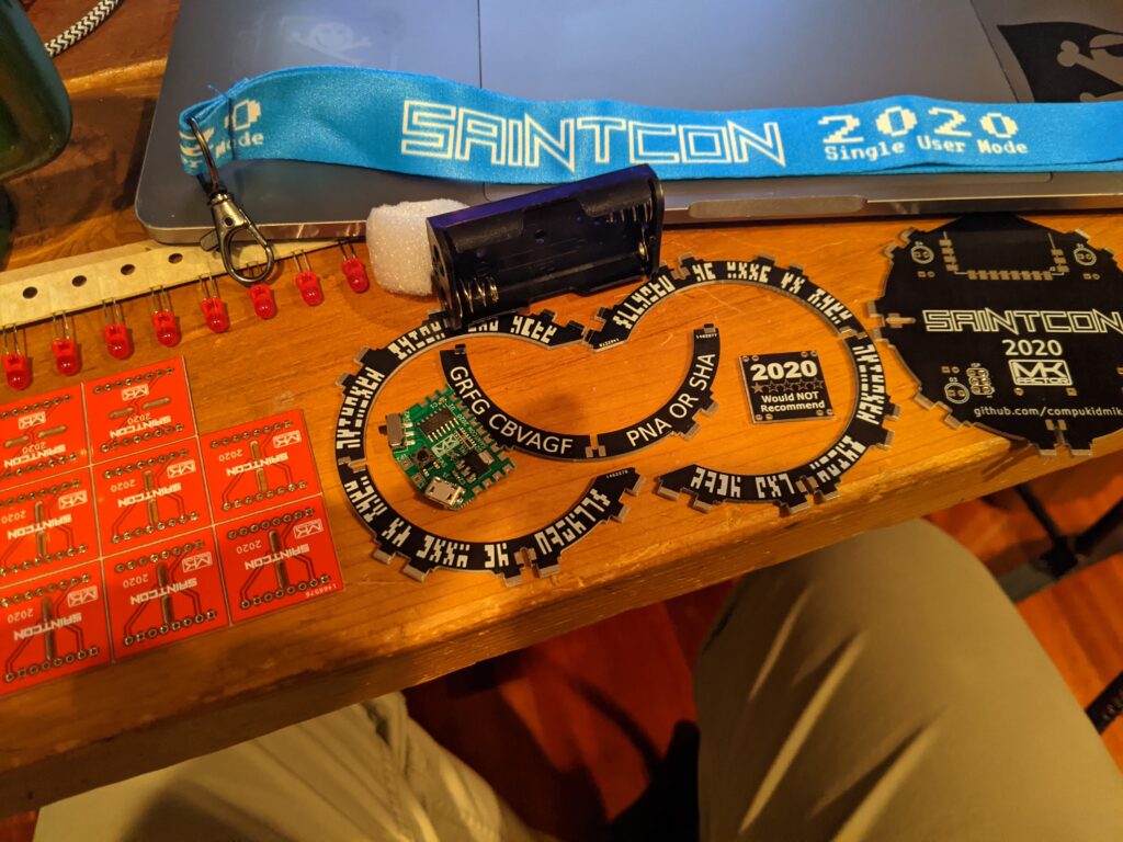
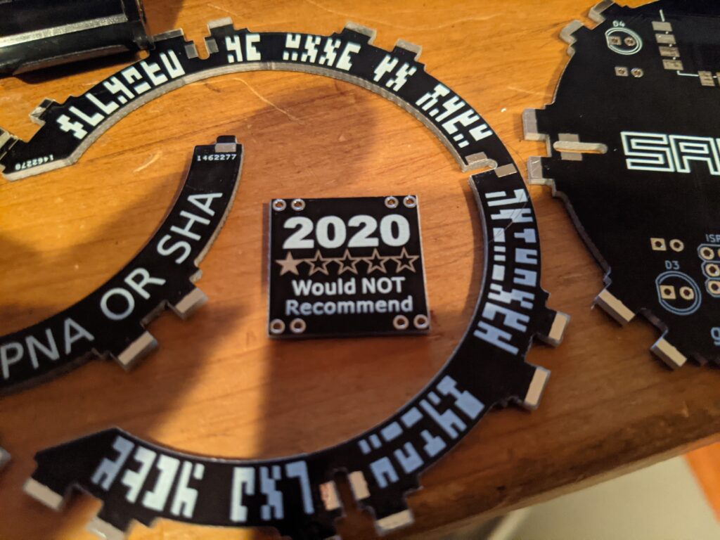
Hey Kyle, look, I took it apart!
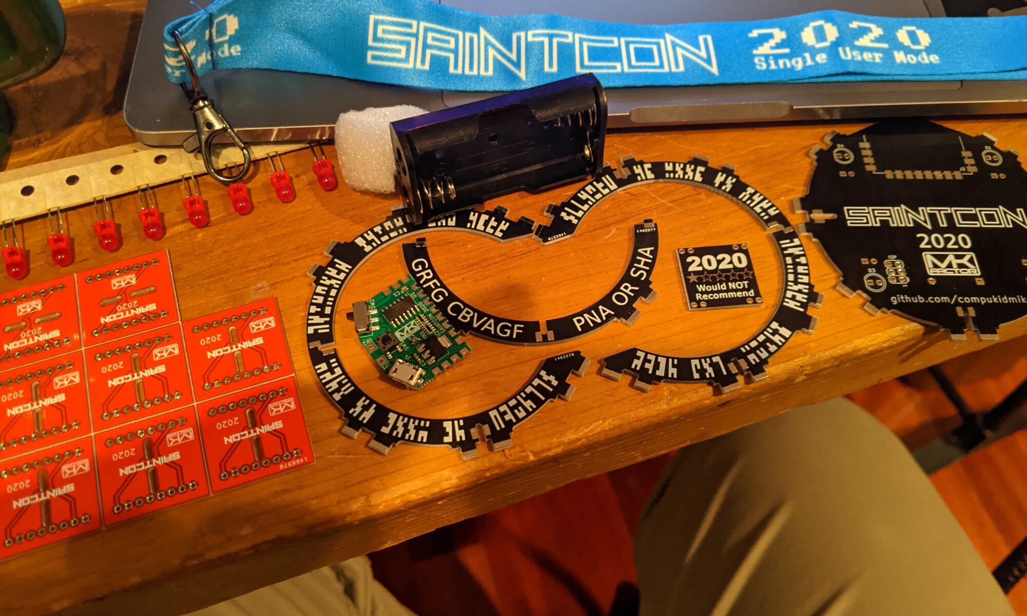
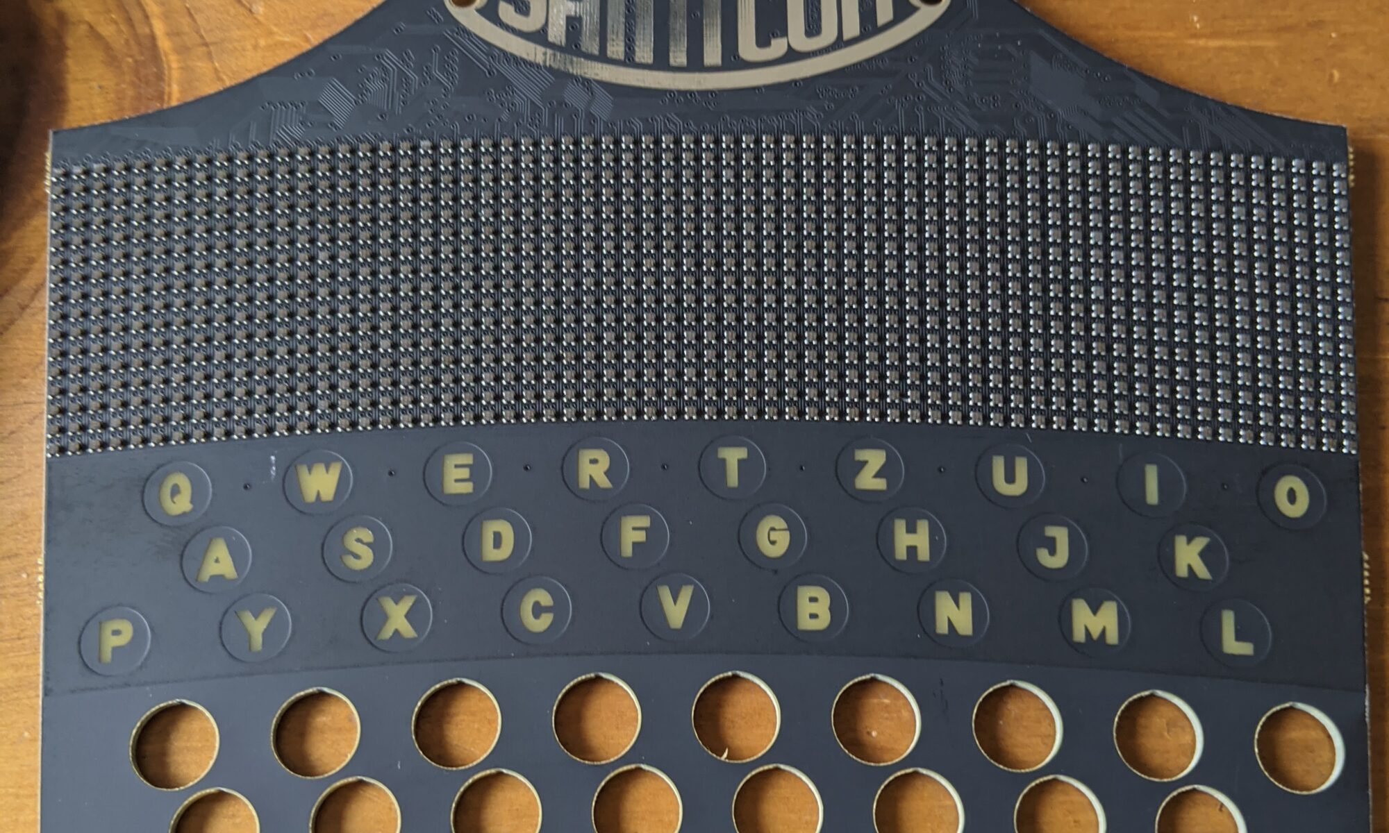
Just kidding. When I was lining up to buy this year’s SAINTCON badge, I saw they had the board/LED display available super cheap, so I bought one. If I can’t have the full ENIGMA badge, at least I can have a fun replica. Never mind that I have no earthly idea how to connect to it to light it up. All in good time, my friends.
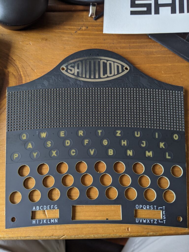
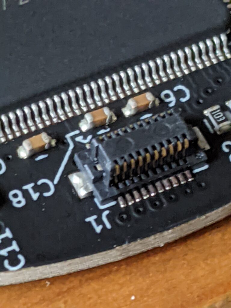
[Update] — OK, I figured out where it connects. That was easy. Just almost too tiny for my poor old man eyes.
New RFID tags arrived
A while back I ordered some stylish (by my standards) Chinese magic writable MiFare RFID fobs. They were clear acrylic with a visible embedded chip. I was excited, even though they were a month away in China.
Well about a week after I ordered them, I got an email from the vendor saying they were out of that model, and gave me three other models to choose from. I didn’t like any of them, but I also didn’t want to start the shopping and ordering process all over again, so I just said, “give me whatever you have.”
They arrived today, and I have to say, I kind of like them. Especially since one of my first clone tests on these fobs will be my daughter’s access card at school. Wish me luck.
SAINTCON Hackers Challenge
SAINTCON’s Hackers Challenge opened up today. I spent a number of hours on it. I nailed the Wireshark tasks, the DD tasks, most of the crypto, and I slayed at Hacker Jeopardy. My weak spots right now are binary analysis and web app exploitation. Might spend more time on it this week and try to get farther along. As of now I’m still in the top five By morning that will be stolen from me. 🙂

Please, take care of your shit, I beg of you
One of the synths I picked up recently was a used Moog Mother32. The seller disclosed correctly. “It’s missing a few faceplate screws, and the wood’s a little banged up, but it works fine.” He wasn’t wrong. I contacted Moog for the replacement screws, because he also failed to provide the screws to the two-tier rack kit that came with it (I have screws that fit, but not in matching black). I figured with a few bucks everything would be good as new, and I can sell the two-tier rack to help fund my gadget habit.
When I went to apply the new screws, I found there was nothing to bite them. Dangit, I thought, now I have to take the extra time, take it back OFF the three-tier rack I had already installed it onto, pop it open and find out why. Of course, the Moog is about as close to Eurorack as you can get without actually going Eurorack, so it’s all Eurorack standard. This means that behind those nice black M3 front panel screws are square M3 slide nuts.
This dude, when he went to sell his gear, installed the bare minimum number of slide nuts in place (three out of eight) that would hold the front panel to the box, and called it a day. Interestingly, it did also include a spare switch. I haven’t noticed any switches malfunctioning yet, so maybe that’s just a spare.
Anyhow, I’ve got some slide nuts coming now, so it’ll be as good as new in a week or so. The Mother32 is the least important piece in my setup, so I’m just going to leave it out for now.
Dude sold it at a great price, so I guess I shouldn’t be complaining, but there’s still a market for this model. Had he just taken the few minutes and few bucks to replace the screws, he could have demanded much more for it.
Oh, and he also didn’t include the manual, so I got one of those from Moog too. At some point when I get bored with it and decide to sell it, I want everything I can get (to help fund whatever unnecessary gadgetry I’m into at that point).


Decoding MIFARE data — pointless?
Now that I can read, dump and clone cards, of course my natural inclinations lead me toward the next goalpost, which is determining what hidden data can be retrieved from the cards. All indications from that forums were that the issue date/time, expiration date/time and room number are stored somewhere on the card, so I knew vaguely what I was looking for, but still had some learning to do.
I wrote a quick script to dump what I know about the cards, which makes it easier to add further definitions as I learn the more detailed structure of the data:
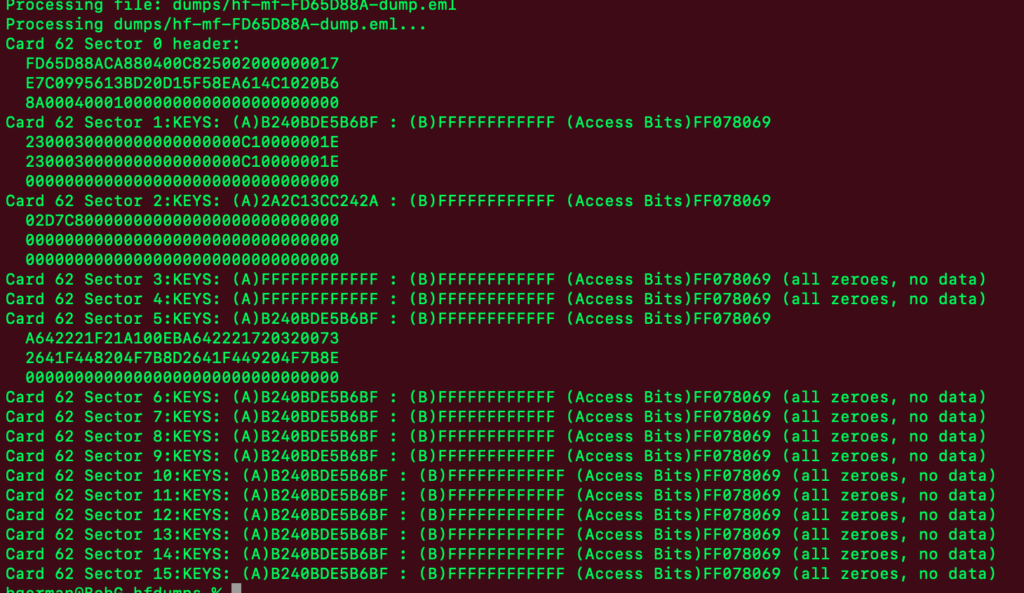
Here’s what I’ve learned so far:
All of the MIFARE cards in my collection (63 of them at last count) have sixteen sector of data. Sector 0 is three blocks and if my understanding is correct, contains immutable manufacturer and other ata. This makes sense, as the very first thing in sector 0 is the UID of the card. What else is that hex data in sector 0? Dunno. Here’s a sector 0 example:
FD65D88ACA880400C825002000000017
E7C0995613BD20D15F58EA614C1020B6
8A000400010000000000000000000000
The bolded hex is the card’s UID.
Sectors 1 through 15 are all four blocks of hex, structured identically. The first block is the keys and access bits. For each sector, there are two keys defined. The access bits define which key or keys are required to read from, or write to, that sector. Example:
2A2C13CC242AFF078069FFFFFFFFFFFF
02D7C800000000000000000000000000
00000000000000000000000000000000
00000000000000000000000000000000
In this case, Key A is 2A2C13CC242A, Key B is FFFFFFFFFFFF, and the access bits field is FF078069, which I found is a very common schema.
The remaining three blocks are data, and here’s where it gets fuzzy. I believe that there is no structure whatsoever to that data. No standard, no default, no pattern. In fact, the bulk of cards had no data stored in most sectors. And I have yet to find a discernible pattern in the data that is stored. I have looked for hex-to-decimal date translations, and so far been unlucky.
Here’s the breakdown of “data stored in sectors”:
Of my 63 cards:
- 48 had data stored in Sector 1
- 34 had data stored in Sector 2
- 3 had data stored in Sector 4
- 5 in Sector 5
- 1 in Sector 6
- 1 in Sector 7
- Zero cards had data stored in Sector 3 or Sectors 8 through 15.
What I’d love to be able to do is to extract the “stay data” from all of these cards. Keep in mind that these are all actual cards from hotels that I and my family have stayed in over the past 4-5 years. So if the data is retrievable, I should be able to cross-reference it to a trip.
And now I just remembered that I have that batch of DEF CON room keys hanging in the basement that should scan and add to the collection.
So here’s my question for the hackers out there. How you determine, or CAN you determine the nature of hex data stored in blocks with no apparent standard of default structure?
The dumps are on https://github.com/dc540/hfdumps if you’re interested in exploring this data.

